Retarder film and polarizing plate

A retardation film and light technology, applied in optics, optical elements, polarizing elements, etc., can solve the problem of difficulty in obtaining the balance between the retardation in the plane direction and the retardation in the thickness direction, and achieve the effect of reliable adjustment, reliable retardation, and small retardation change.

Inactive Publication Date: 2013-12-25
KEIWA INCORPORATED
View PDF5 Cites 0 Cited by
  • Summary
  • Abstract
  • Description
  • Claims
  • Application Information

AI Technical Summary

Problems solved by technology

Therefore, a solvent remains in the retardation film described in the publication, and there is a problem that it is difficult to achieve a balance between retardation in the plane direction and retardation in the thickness direction due to the residual solvent.

Method used


Image

  • Retarder film and polarizing plate
  • Retarder film and polarizing plate
  • Retarder film and polarizing plate

Examples


Embodiment 1

[0109] Examples of the retardation film of the present invention will be described below.

[0110]In this example, the following sheet-forming material was prepared by adding 5 wt. TPP of Daihachi Chemical Industry and 5 parts by weight of #10 of Daihachi Chemical Industry. The sheet-forming material was melted and extruded through a T-die to obtain a sheet-shaped sheet-forming material, and the sheet-shaped sheet-forming material was stretched at a stretching temperature of 155° C. at a stretch ratio of 165%, The retardation film of this example was obtained. In addition, the average thickness of the retardation film was 145 μm (240 μm before stretching).

[0111] For the retardation film of the above example, the transmitted light for each wavelength was measured under the environment of 23° C. and 50% RH with an automatic birefringence measuring device (manufactured by Oji Scientific Instruments Co., Ltd., trade name: KOBRA-WR). face direction delay. The results are sho...

Embodiment approach

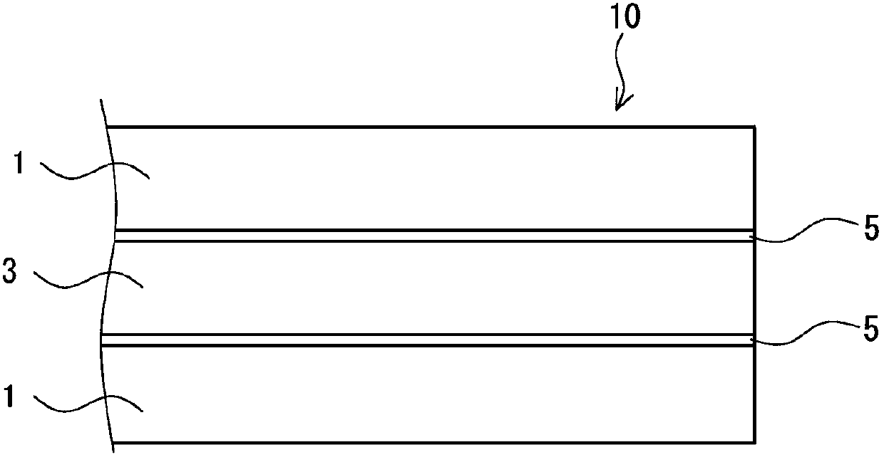
[0117] In addition, this invention is not limited to the said embodiment, Various deformation|transformation and improvement are possible. For example, the polarizing plate 10 of the above-described embodiment has been described as a polarizing plate having a three-layer structure (excluding the adhesive layer 5 ) including a pair of retardation films 1 and a polarizing plate 3 sandwiched therebetween. Change the design so that the polarizing plate 10 has, for example, a two-layer structure of the polarizer 3 and the retardation film 1. In addition, it can also be adopted on the three-layer structure of the above-mentioned embodiment. Laminated protective film structure.


PUM

PropertyMeasurementUnit
thicknessaaaaaaaaaa
thicknessaaaaaaaaaa
thicknessaaaaaaaaaa

Abstract

The invention aims to provide a retarder film and a polarizing plate capable of easily and reliably adjusting the retardation and facilitating the layered adhesion process. In addition, the retardation caused by different application environmental conditions is relieved. The retarder film is formed through stretching an extruded CAP resin sheet. When the retardation value is measured to be R448, R589 and R800 by means of the light of 448.1 nm, the light of 589 nm and the light of 800 nm respectively and correspondingly, the (R800 / R589-R448 / R589) / (800-589) value of the retarder film is preferably larger than 0.001 and smaller than 0.003.

Description

technical field [0001] The present invention relates to a retardation film and a polarizing plate. Background technique [0002] Conventionally, there is known a retardation film formed by stretching a polycarbonate sheet or a cycloolefin polymer sheet. The retardation film is used, for example, in a polarizing plate. Specifically, a polarizer is formed by laminating a polarizer protective film made of cellulose triacetate or the like on both surfaces of a polarizer (polarizer), and the retardation film is formed by applying a water-based glue (water paste) or the like to the polarizer. The polarizer is laminated and glued on the polarizer to manufacture a polarizer. [0003] The resin of the polycarbonate retardation film has a relatively high photoelastic coefficient of 60 to 80. If the polycarbonate retardation film is deformed by the temperature and humidity of the use environment, the refractive index will change and retardation will occur. changing issues. Therefor...

Claims


Application Information

Patent Timeline
Patent Type & Authority Applications(China)
IPC IPC(8): G02B5/30G02F1/1335
CPCB29D7/01B32B27/08C08J5/18C08J2301/12C08L1/12C08L2203/16G02B5/3033G02F1/13363
Inventor 峯尾裕
Owner KEIWA INCORPORATED
Why Eureka
Try Eureka