A blue-phase liquid crystal display with continuously controllable viewing angle

A blue-phase liquid crystal and display technology, applied in instruments, nonlinear optics, optics, etc., can solve the problems of high cost, low contrast, and complicated viewing angle controllable liquid crystal display technology, and achieve good color display, color display, viewing angle, etc. Continuously controllable effects

Active Publication Date: 2016-08-31
HEBEI UNIV OF TECH
View PDF7 Cites 0 Cited by
  • Summary
  • Abstract
  • Description
  • Claims
  • Application Information

AI Technical Summary

Problems solved by technology

[0005] The purpose of the present invention is to overcome the shortcomings existing in the prior art and solve the problems of traditional viewing angle controllable liquid crystal displays with complex process, high cost and low contrast ratio under narrow viewing angles

Method used


Image

  • A blue-phase liquid crystal display with continuously controllable viewing angle
  • A blue-phase liquid crystal display with continuously controllable viewing angle
  • A blue-phase liquid crystal display with continuously controllable viewing angle

Examples


Embodiment 1

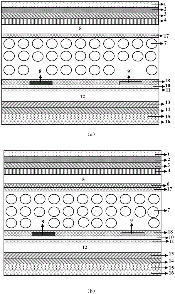
[0029] Such as figure 1 As shown, a blue-phase liquid crystal display with continuously controllable viewing angle, its composition from top to bottom is: upper polarizer 1, upper λ / 4 biaxial film 2, upper λ / 2 negative A plate 3, upper λ / 4 Positive A plate 4, upper glass substrate 5, first Common electrode 6, first protective layer 17, blue phase liquid crystal 7, second protective layer 18, electrode layer (first Pixel electrode 8 and second Pixel electrode 9), A silicon dioxide layer 10 , a second common electrode 11 , a lower glass substrate 12 , a lower λ / 4 negative A plate 13 , a lower λ / 2 positive A plate 14 , a lower λ / 4 biaxial film 15 and a lower polarizer 16 . Wherein the second protection layer 18 covers the first Pixel electrode 8 and the second Pixel electrode 9 , and the first Pixel electrode 8 and the second Pixel electrode 9 are on the silicon dioxide layer 10 .

[0030] The preferred direction of the transmission axis of the lower polarizer 16 is 0°, the dir...

Embodiment 2

[0045] It has the same hierarchical structure and parameter settings as Embodiment 1, and the differences from Embodiment 1, such as Figure 5 As shown, the top view of the arrangement and distribution of the first Pixel electrodes and the second Pixel electrodes, the electrodes are arranged in a zigzag structure, and the included angle of the zigzag electrodes is 90 degrees. The width and pitch of the zigzag electrodes were 2 and 8 μm, respectively. The effect of continuously changing the viewing angle is the same as that of Embodiment 1.

Embodiment 3

[0047] It has the same hierarchical structure and parameter settings as Embodiment 1, and the differences from Embodiment 1, such as Figure 6 As shown, the top view of the arrangement and distribution of the first Pixel electrodes and the second Pixel electrodes, and the arrangement of the electrodes is a horizontal and vertical arrangement structure. The width and pitch of the electrodes were 2 and 8 μm, respectively. The effect of continuously changing the viewing angle is the same as that of Embodiment 1.


PUM

PropertyMeasurementUnit
thicknessaaaaaaaaaa
thicknessaaaaaaaaaa
widthaaaaaaaaaa

Abstract

The present invention is a blue-phase liquid crystal display with continuously controllable viewing angle, and its composition from top to bottom is as follows: upper polarizer, upper λ / 4 biaxial film, upper λ / 2 negative A plate, upper λ / 4 positive A sheet, upper glass substrate, first common electrode, first protective layer, blue phase liquid crystal, second protective layer, electrode layer, insulating layer, second common electrode, lower glass substrate, lower λ / 4 negative A plate, lower λ / 2 positive A film, lower λ / 4 biaxial film and lower polarizer; the electrode layer is the first Pixel electrode and the second Pixel electrode, distributed at intervals. The invention successfully overcomes the disadvantage that the contrast ratio of the traditional viewing angle controllable blue phase liquid crystal display is only 10 to 30 in the narrow viewing angle. Moreover, by applying different bias voltages to the bias electrodes, a viewing angle with different display effects and a narrow viewing angle mode in which the contrast ratio changes continuously can be obtained.

Description

technical field [0001] The present invention designs a device in the field of liquid crystal display technology, specifically a blue-phase liquid crystal display device with continuously controllable viewing angle Background technique [0002] With the development of information society, information protection has attracted more and more attention. For example, some portable display devices, mobile phones, notebook computers, ATM machines, etc. They are often used in public places. In order to protect personal privacy and important information, they need to have a display feature of a narrow viewing angle, but in private places, they need to have a display feature of a wide viewing angle. Therefore, in the future, liquid crystal displays need to have a viewing angle control feature. [0003] The blue phase liquid crystal display has the characteristics of response time below milliseconds, wide viewing angle and high contrast ratio, and does not require an alignment layer i...

Claims


Application Information

Patent Timeline
Patent Type & Authority Patents(China)
IPC IPC(8): G02F1/1343G02F1/137
Inventor 孙玉宝李岩锋赵彦礼
Owner HEBEI UNIV OF TECH
Why Eureka
Try Eureka