Lane line detection method and device

A technology of lane line detection and right lane, applied in the field of intelligent transportation, can solve the problem of inability to obtain the correct lane line, and achieve the effect of high accuracy

Active Publication Date: 2013-12-25
CHERY AUTOMOBILE CO LTD
View PDF2 Cites 24 Cited by
  • Summary
  • Abstract
  • Description
  • Claims
  • Application Information

AI Technical Summary

Problems solved by technology

[0006] In order to solve the problem that the existing technology cannot obtain the correct lan

Method used


Image

  • Lane line detection method and device
  • Lane line detection method and device
  • Lane line detection method and device

Examples


Embodiment 1

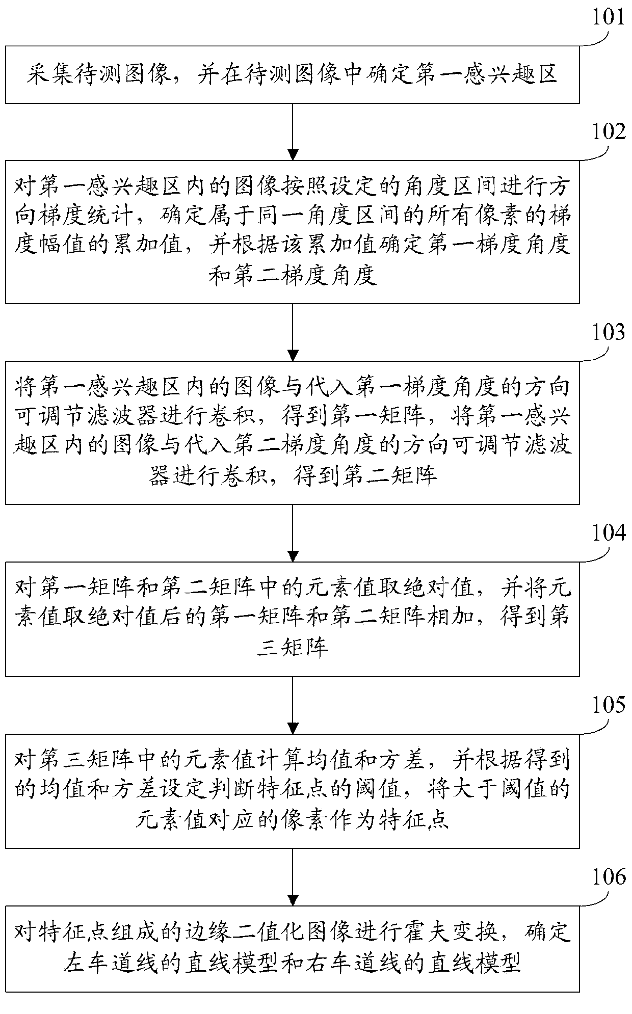
[0063] An embodiment of the present invention provides a lane line detection method, see figure 1 , the method includes:

[0064] Step 101: Collect an image to be tested, and determine a first region of interest in the image to be tested.

[0065] In this embodiment, the first region of interest is all or part of the area below the vanishing line of the ground plane and within the left and right boundaries in the field of view of the image-to-be-tested acquisition device.

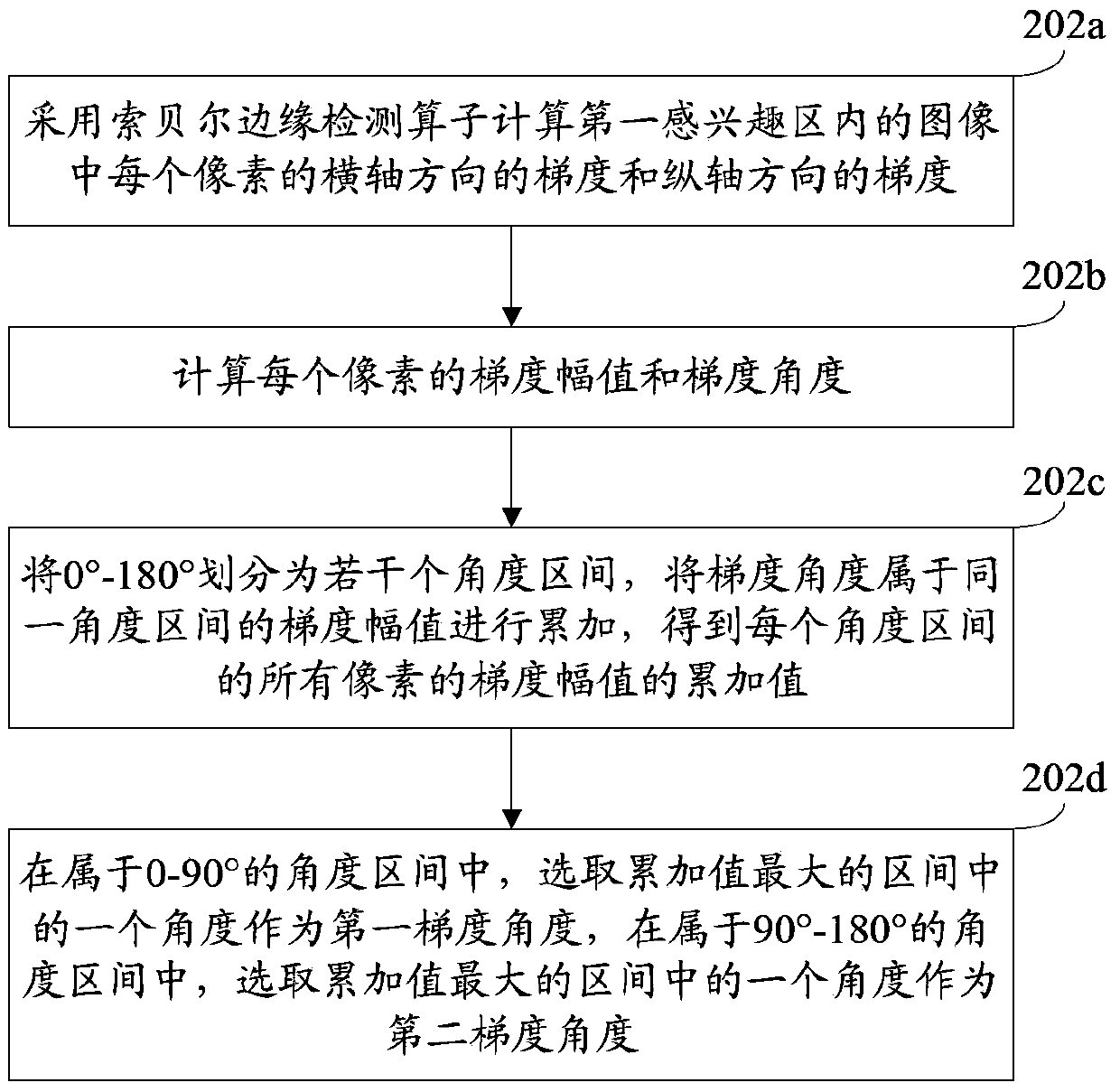
[0066] Step 102: Perform directional gradient statistics on the image in the first region of interest according to the set angle interval, determine the cumulative value of the gradient magnitude of all pixels belonging to the same angular interval, and determine the first gradient angle and Second gradient angle.

[0067] In this embodiment, the first gradient angle belongs to 0-90°, and the second gradient angle belongs to 90°-180°.

[0068] Step 103: Convolute the image in the first region of interest...

Embodiment 2

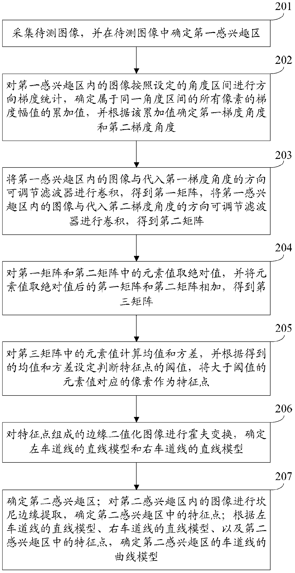
[0074] An embodiment of the present invention provides a lane line detection method, see figure 2 , the method includes:

[0075] Step 201: Collect an image to be tested, and determine a first region of interest in the image to be tested.

[0076] In this embodiment, the first region of interest is all or part of the area below the vanishing line of the ground plane and within the left and right boundaries in the field of view of the image-to-be-tested acquisition device.

[0077] In a practical application, the image to be tested is an image of the road condition in front of the vehicle, which can be collected by a camera installed inside or outside the vehicle.

[0078] Optionally, determining the first region of interest may include: taking the part below the vanishing line of the ground plane in the image to be tested as the first region of interest, reducing the time of lane line detection and improving the accuracy of lane line detection.

[0079] Preferably, determin...

Embodiment 3

[0117] An embodiment of the present invention provides a lane line detection device, see Figure 5 , applicable to a lane line detection method provided in Embodiment 1, the device includes:

[0118] The image acquisition module 301 is configured to acquire the image to be tested, and determine a first region of interest in the image to be tested, where the first region of interest is below the vanishing line of the ground plane and within the left and right boundaries in the field of view of the acquisition device of the image to be tested all or part of the area;

[0119] The gradient statistics module 302 is used to perform directional gradient statistics on the images in the first region of interest according to the set angle interval, determine the cumulative value of the gradient magnitudes of all pixels belonging to the same angular interval, and determine the first The gradient angle and the second gradient angle, the first gradient angle belongs to 0-90°, and the sec...


PUM


Abstract

The invention discloses a lane line detection method and a lane line detection device and belongs to the field of intelligent traffic. The lane line detection method comprises the following steps: acquiring an image to be detected, and determining a first region of interest in the image to be detected; determining an accumulated value of gradient magnitudes of all the pixels in the same angle interval, and determining a first gradient angle and a second gradient angle according to the accumulated value; carrying out convolution on the image in the first region of interest and a direction adjustable filter respectively substituted by the first gradient angle and the second gradient angle, so as to obtain a first matrix and a second matrix; getting absolute values of element values in the first matrix and the second matrix, and adding the first matrix with the second matrix after the absolute values of the element values are got, so as to obtain a third matrix; calculating mean value and variance of element values in the third matrix, so that a threshold value is obtained, and pixels corresponding to the element values higher than the threshold value are taken as feature points; and carrying out Hough transformation on an edge binarization image composed of the feature points, and determining a straight line model of a lane line. The lane line detection method and the lane line detection device have the advantage that accuracy of detection on the lane line is high.

Description

technical field [0001] The invention relates to the field of intelligent transportation, in particular to a lane line detection method and device. Background technique [0002] Lane line detection technology refers to the technology of detecting virtual and real road markings by means of image sensing and other means. Using the lane line detection technology, it can prevent the car from deviating from the lane, and can also give the driver a warning message when the vehicle deviates or has a tendency to deviate, reminding the driver to take measures to prevent accidents. Therefore, lane line detection is very important for the driving safety of the car. [0003] The existing lane line detection methods include: using Sobel (Sobel) edge detection operator to calculate the gradient of each pixel in the image to be tested; determining the pixel whose gradient is greater than a fixed threshold as a lane line feature point; according to the determined lane line feature Point, u...

Claims


Application Information

Patent Timeline
IPC IPC(8): G06T7/00
Inventor 王海陈军孙锐王继贞
Owner CHERY AUTOMOBILE CO LTD
Why Eureka
Try Eureka