
A high-speed transfer switching device

A transfer switch and electric appliance technology, applied in the field of electromechanical, can solve the problems of difficult assembly, slow action speed, complex structure, etc., and achieve the effect of short switching time, high reliability, simple and reasonable structure

Active Publication Date: 2016-04-20
GUIZHOU TAIYONG CHANGZHENG TECH CO LTD
View PDF5 Cites 0 Cited by
  • Summary
  • Abstract
  • Description
  • Claims
  • Application Information

AI Technical Summary

Problems solved by technology

Its structure is complicated, the assembly is difficult, and the movement speed is slow.

Method used


Image

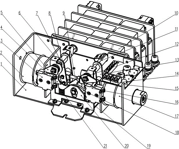
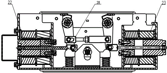
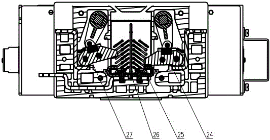
  • A high-speed transfer switching device
  • A high-speed transfer switching device
  • A high-speed transfer switching device

Examples


Embodiment Construction

[0019] In order to greatly shorten the switching time of high-speed switching electrical appliances, and to control the time of the two-point state in the contact switching process within a very short range, the present invention provides a new switching mechanism, so that the switching can be completed in a very short time. And the structure is simple and reliable.

[0020] Such as figure 1 , figure 2 , image 3 As shown, a new type of high-speed transfer switching device is mainly composed of a transfer mechanism part and a body part 10. The conversion mechanism part is mainly composed of bracket assembly 1, A power direction electromagnet assembly 2, A auxiliary switch 3, support member 4, A pressure plate 5, A power supply square shaft assembly 6, A swing arm 7, A roller 8, and an intermediate link Component 9, B power supply square shaft component 11, B pressure plate 12, B swing arm 13, B roller 14, circuit board component 15, B auxiliary switch 16, B power supply di...


PUM


Abstract

The invention relates to high-speed transfer switching equipment. The high-speed transfer switching equipment is mainly composed of a transfer mechanism part and a body part, wherein the transfer mechanism part is composed of a support assembly, an A power supply direction electromagnet assembly, an A auxiliary switch, a supporting piece, an A pressing plate, an A power supply square shaft assembly, an A swing arm, an A idler wheel, a middle connecting rod assembly, a B power supply square shaft assembly, a B pressing plate, a B swing arm, a B idler wheel, a circuit board assembly, a B auxiliary switch, a B power supply direction electromagnet assembly, a cam sliding block assembly, a right spring, a fixed base, a left spring, an A power supply electromagnetic assembly movable iron core and a B power supply electromagnetic assembly movable iron core, the body part is composed of a shell, an A power supply moving contact assembly, a static contact assembly, an arc-control device and a B power supply moving contact assembly, a transfer mechanism controls connection and disconnection of an A power supply moving contact and a B power supply moving contact by means of the double electromagnet assemblies which are arranged symmetrically, mechanical self-locking is achieved by means of the cam sliding block assembly, and the auxiliary switches are used for electric interlocking.

Description

technical field [0001] The invention belongs to the field of electromechanical technology, and in particular relates to a high-speed transfer switch electrical appliance. Background technique [0002] At present, most of the general-purpose automatic transfer switch appliances on the market use a single electromagnet to provide the power source, which requires a special locking electromagnet and a complex locking mechanism to achieve mechanical self-locking, and requires a special reversing electromagnet and corresponding switching devices. To the mechanism to complete the reversing action. Since the conversion process includes the electromagnet touch time, the mechanical self-locking mechanism trip time and the double digit time, the conversion time is long. Its structure is complicated, assembly difficulty is big, and action speed is slow. Contents of the invention [0003] In order to overcome the above-mentioned defects, the object of the present invention is to prov...

Claims


Application Information

Patent Timeline
Patent Type & Authority Patents(China)
IPC IPC(8): H01H9/26H01H3/28
Inventor 黄正乾黄仁武
Owner GUIZHOU TAIYONG CHANGZHENG TECH CO LTD
Learn More