stamping die

A technology for stamping molds and mold shells, applied in the field of molds, which can solve the problems of increasing the stroke of the punch, consuming time, and injuring people's hands, so as to speed up the stamping speed, eliminate potential safety hazards, and improve work efficiency.

Inactive Publication Date: 2015-10-28
TAIZHOU XINGYU SPORTS TACKLE
View PDF7 Cites 0 Cited by
  • Summary
  • Abstract
  • Description
  • Claims
  • Application Information

AI Technical Summary

Problems solved by technology

[0003] The stamping dies of the prior art have the following defects: each time a screw is punched, five steps of mold opening, loading, stamping mold clamping, mold opening, and demoulding need to be carried out separately, and as many screws as needed to be stamped need to be repeated as many times as necessary. The speed is slow and the efficiency is low, and continuous stamping and forming cannot be performed; secondly, because the round bar is placed between the upper mold and the lower mold when discharging, in this way, if the mold opening range is too small before discharging and when the mold is opened, two The distance between the molds is not enough, it is difficult for people to put the round rod in, but if the mold opening range is too large, the stroke of the punch will be increased when the mold is opened and closed, which will consume more time and further reduce the efficiency. There is a certain danger in discharging the material between the two molds. If the punch is accidentally activated, it may hurt the hands; moreover, because the opening of the lower mold is facing upwards, the demoulding process is too inconvenient

Method used


Image

  • stamping die
  • stamping die
  • stamping die

Examples


Embodiment Construction

[0019] The present invention will be further described below in conjunction with the accompanying drawings and specific embodiments.

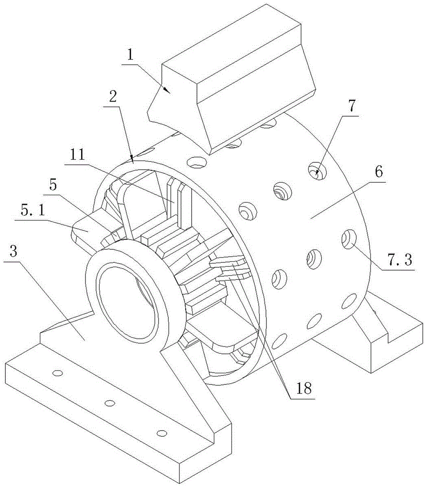
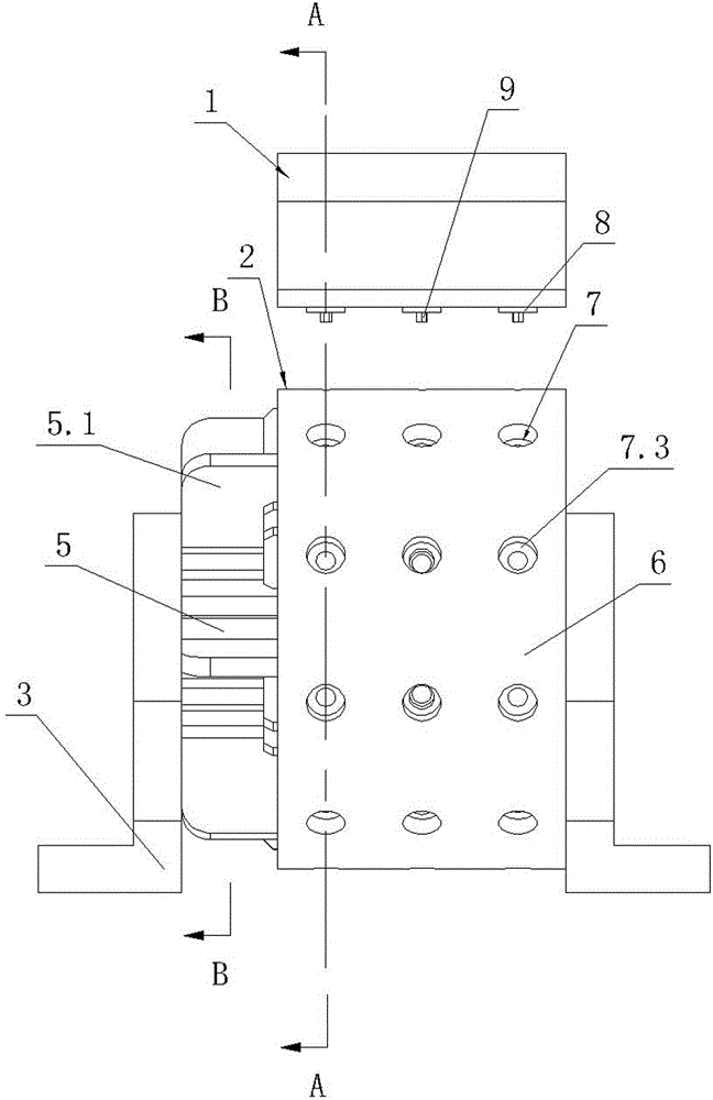
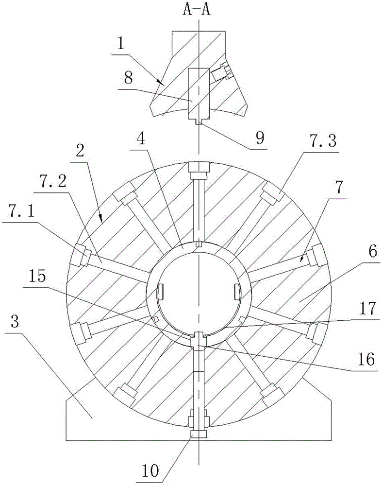
[0020] Such as figure 1 , figure 2 , image 3 , Figure 4 As shown, the stamping die of the present invention includes a punch 1 and a die shell 2. The formwork 2 includes two supports 3 , a rotating shaft 4 , a toggle gear 5 and a rotating cylinder 6 . The two ends of the rotating shaft 4 are respectively fixed to the two supports 3, the toggle gear 5 is rotatably fitted on the rotating shaft 4 and the toggle gear 5 is provided with a plurality of paddles 5.1 radially protruding outward. A ratchet device is provided between the toggle gear 5 and the rotating shaft 4, that is, a ratchet 12 is provided on the shaft section of the rotating shaft 4 that fits with the toggle gear 5, and the center hole of the toggle gear 5 fits on the ratchet 12 and the toggle gear The center hole of 5 is provided with elastic ratchet 13. A locking slot 14 i...


PUM


Abstract

The invention discloses a punching die, which comprises a punch (1) and a die shell (2), wherein the die shell (2) comprises two supports (3), a rotating shaft (4), a shifting gear and a rotating barrel (6), the two ends of the rotating shaft (4) are fixed with the two supports (3), the shifting gear and the rotating shaft (4) are registered, a ratchet gear is arranged between the shifting gear and the rotating shaft (4), the rotating barrel (6) is rotatably registered on the rotating shaft (4), a plurality of radial through holes (7) are formed in the rotating barrel (6), the outer openings of the radial through holes (7) are arrayed in the outer circumferential surface of the rotating barrel (6) in rows along the axial direction, the punch (1) is provided with a plurality of rams (8), all of the row of rams (8) are over against the row of radial through holes (7) on the highest position of the rotating barrel (6), and the rotating shaft (4) is also provided with a device for releasing a punching forming screw (10) from the radial through holes (7) in an ejecting manner. The punching die enables the speed of a punching process to be high, the efficiency is high, and safety and convenience are realized.

Description

technical field [0001] The invention relates to the technical field of molds, in particular to a stamping mold for stamping screws. Background technique [0002] The stamping die of the traditional stamping screw includes a lower die and an upper die. The upper end of the lower die is provided with a blind hole that matches the shape of the screw, that is, the lower die cavity. The lower end of the upper die is provided with cylindrical pits. The top is provided with hexagonal prism protrusions, and the cavity between the cylindrical recess and the hexagonal prism protrusions constitutes an upper die cavity that matches the shape of the head of the hexagon socket head screw, and the centerlines of the upper and lower die cavities coincide. Fix the lower mold, and put a round rod into the lower mold cavity. The length of the round rod is greater than the height of the lower mold cavity, and the upper mold and the punch are fixed. Drive the punch to make the two molds close to...

Claims


Application Information

Patent Timeline
Patent Type & Authority Patents(China)
IPC IPC(8): B21D37/10B21D53/24
Inventor 陆昱森
Owner TAIZHOU XINGYU SPORTS TACKLE
Why Eureka
Try Eureka