
Rings for ring spinning machines or ring twisting machines

A technology of ring spinning machine and twisting machine, which is applied in the ring field of ring spinning machine or ring twisting machine, can solve the problems that the comprehensive performance of steel ring and traveler cannot be fundamentally improved, and achieve Reduce yarn breakage, improve yarn quality, and increase output

Active Publication Date: 2016-03-30
CHONGQING JINMAO TEXTILE ACCESSORIES
View PDF6 Cites 0 Cited by
  • Summary
  • Abstract
  • Description
  • Claims
  • Application Information

AI Technical Summary

Problems solved by technology

Since the friction spinning between the steel ring and the traveler is sliding friction, wear is still the main reason for the failure of the steel ring and the traveler. The above methods cannot fundamentally improve the comprehensive performance of the steel ring and the traveler.

Method used


Image

  • Rings for ring spinning machines or ring twisting machines
  • Rings for ring spinning machines or ring twisting machines
  • Rings for ring spinning machines or ring twisting machines

Examples


Embodiment 2

[0031] Other structures are identical with embodiment 1, and difference is: as Figure 7 As shown, the outer wall of the middle section of the runner 3 has an annular groove, the outer circumference of the ring swivel 2 is inserted into the annular groove of the runner 3, and the ring swivel 2 is provided with a through hole 2b , the through hole 2b is located outside the annular groove of the runner 3. The yarn passes through the through hole 2b, driven by the spindle 10 and the yarn, the ring swivel 2 rotates accordingly.


PUM


Abstract

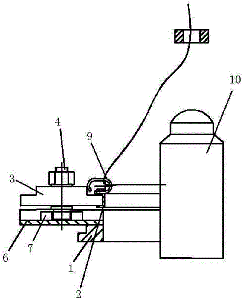
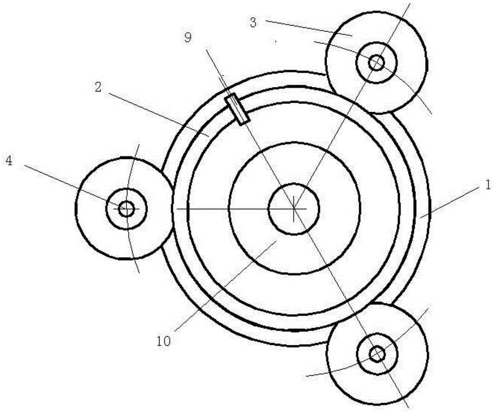
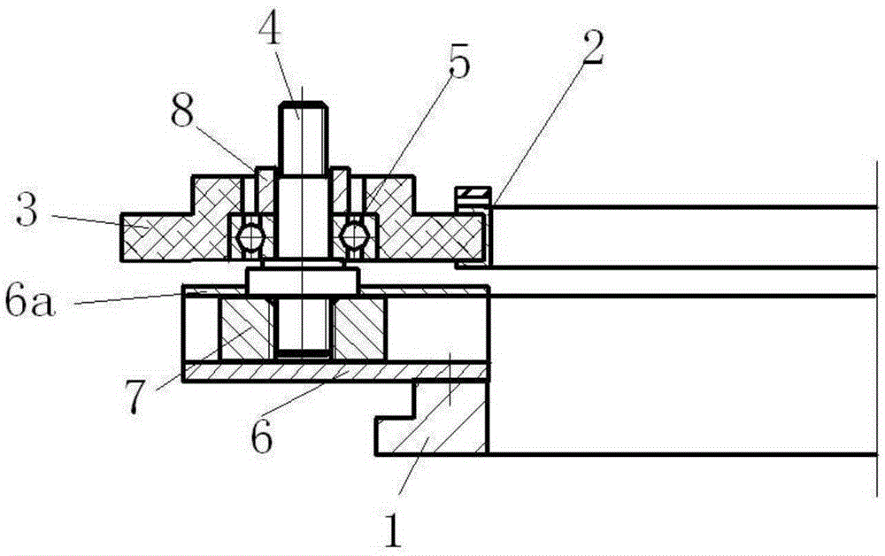
The invention discloses a steel collar for a ring spinner or a ring twister. The steel collar is characterized by comprising a steel collar fixing base (1), steel collar rotating rings (2), rotating wheels (3) and rotating wheel shafts (4). The steel collar fixing base (1) and the steel collar rotating rings (2) are ring-shaped. The outer diameter of the steel collar fixing base (1) is larger than that of the steel collar rotating rings (2). The steel collar fixing base (1) is evenly provided with at least three rotating wheel bases. The rotating wheel shafts (4) are installed on the rotating wheel bases. Each rotating wheel shaft (4) is movably sleeved with one rotating wheel (3). Center lines of the rotating wheels (3) are located on the same ring. The steel collar rotating rings (2) are installed on the rotating wheels (3) in an inserting mode after being connected in a butting mode, and can rotate relative to the rotating wheels (3). The rotating wheels (3) limit the steel collar rotating rings (2) in the radial direction. The service life of a bead ring and the steel collar is greatly prolonged.

Description

technical field [0001] The invention relates to a component of a ring spinning machine and a ring twisting machine, in particular to a steel ring for a ring spinning machine or a ring twisting machine. Background technique [0002] The existing ring spinning machine realizes the twisting and winding of the cotton yarn through the cooperating movement of the spindle, the steel ring, the traveler and other parts (such as Chinese patent 95514053), wherein the steel ring is in the shape of a ring, and on the spinning machine In a fixed state, the spindle is at the center of the inner circle of the steel ring, the traveler is installed on the track of the steel ring, the yarn is hung on the traveler, and the yarn is wound with the rotation of the spindle, and the yarn drives the traveler along the inner circumference of the steel ring The runway slides at a high speed at a speed of 30-40m / s. [0003] The traveler slides on the ring track at high speed, which generates a large ce...

Claims


Application Information

Patent Timeline
Patent Type & Authority Patents(China)
IPC IPC(8): D01H7/60
Inventor 徐兴远王可平赵仁兵
Owner CHONGQING JINMAO TEXTILE ACCESSORIES
Learn More