Wind brace

A technology of wind braces and slide rails, which is applied in the direction of building fastening devices, wing leaf fastening devices, buildings, etc., can solve the problems of inconvenient use and unfavorable use safety of window sash, and achieve the effect of safe and convenient use

Inactive Publication Date: 2014-01-01
ANHUI XIN FA ALUMINUM PROD
View PDF0 Cites 2 Cited by
  • Summary
  • Abstract
  • Description
  • Claims
  • Application Information

AI Technical Summary

Problems solved by technology

In the prior art, wind braces are generally fixed firmly by manual twisting, which is very inconvenient to use and is not conducive to the safe use of window sash.

Method used


Image

  • Wind brace
  • Wind brace

Examples


Embodiment Construction

[0014] The present invention will be further described in detail below in conjunction with the accompanying drawings and specific embodiments.

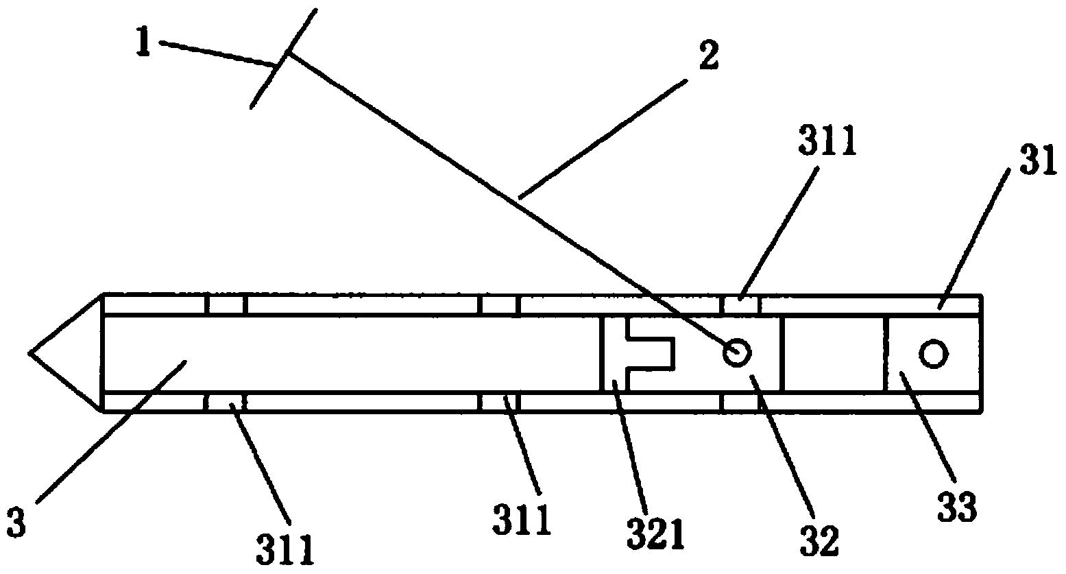
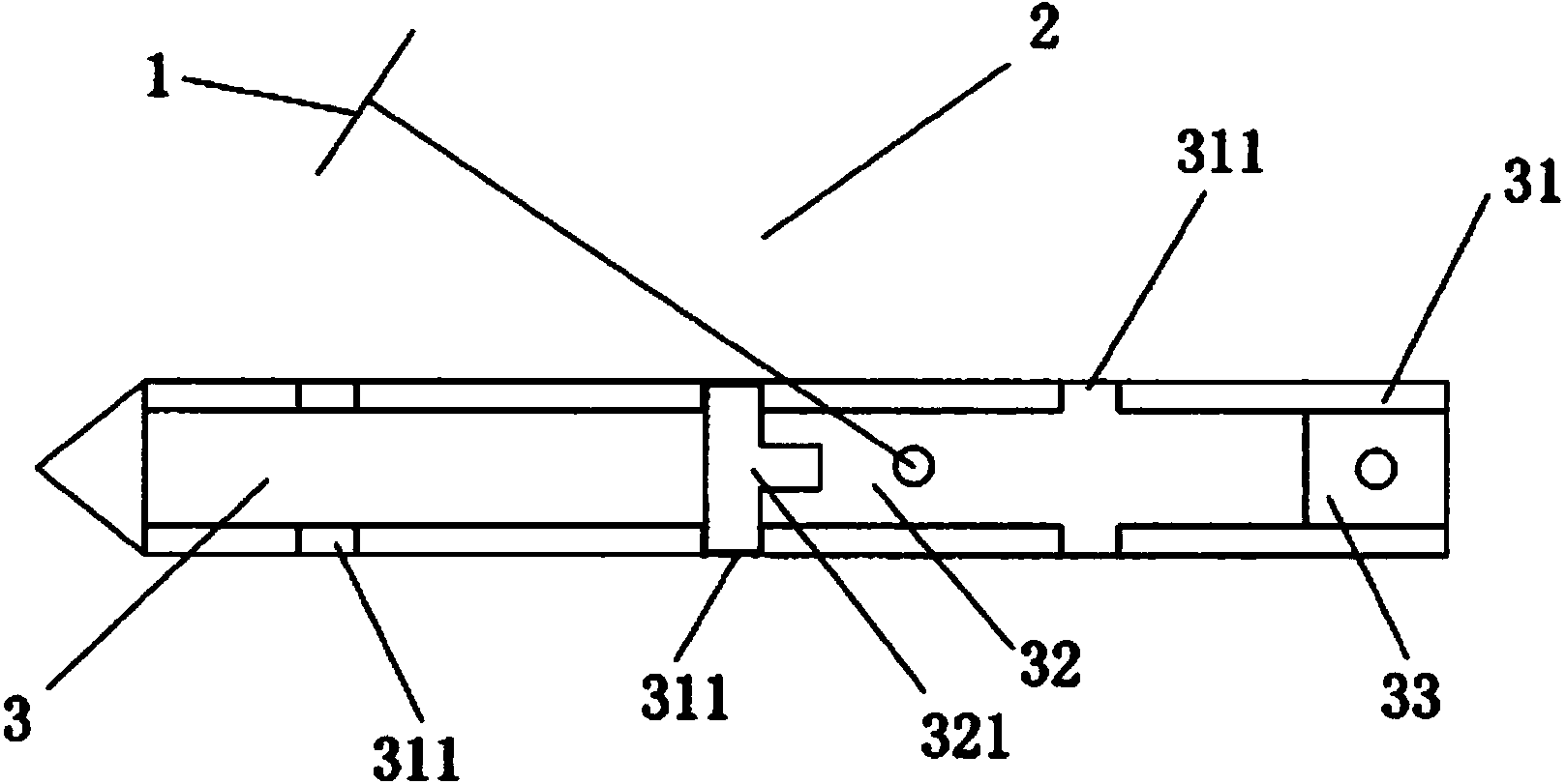
[0015] Such as figure 1 , figure 2 As shown, a wind brace includes a slide rail body 3, a connecting rod 2 connected to the slide rail body 3 and a locking piece 1 connected to the connecting rod 2, wherein the side of the slide rail body 3 A sliding groove 31 is provided at the part, and a sliding piece 32 is arranged in the sliding groove 31. One end of the connecting rod 2 is connected with the locking piece 1, and the other end is connected with the sliding piece 32; A guide rail plate 321 is provided on the sheet 32 ​​, and an inner notch 311 correspondingly matched with the guide rail plate 321 is provided on the slide groove 31 .

[0016] The side of the slide rail body 3 is provided with a slide groove 31, and a slide plate 32 is arranged in the slide groove 31, and the slide plate 32 can move along the slide groove 31, and...


PUM


Abstract

The invention discloses a wind brace which is characterized by comprising a sliding rail body, a connection rod connected with the sliding rail body and a locking sheet connected with the connection rod. A sliding groove is formed in the side portion of the sliding rail body. A sliding sheet is arranged in the sliding groove. One end of the connection rod is connected with the locking sheet and the other end of the connection rod is connected to the sliding sheet. A guide rail plate is arranged on the sliding sheet. An inwards-concave opening matched with the guide rail plate is formed in the sliding groove. The wind brace can be automatically fixed and fastened and is convenient to use.

Description

technical field [0001] The invention relates to a spare part of a door and window, in particular to a wind brace. Background technique [0002] The wind brace is a window sash fixing device that makes the window sash open to a certain angle according to needs, and restricts the window sash from swinging freely due to wind pressure. In the prior art, the wind brace is generally fixed firmly by manual twisting, which is inconvenient to use and is not conducive to the safe use of the window sash. Contents of the invention [0003] The technical problem to be solved by the present invention is to provide a wind brace that can be automatically fixed firmly and is easy to use. [0004] In order to solve the problems of the technologies described above, the technical solution adopted in the present invention is: [0005] A wind brace, comprising a slide rail body, a connecting rod connected to the slide rail body and a locking piece connected to the connecting rod, wherein a sl...

Claims


Application Information

Patent Timeline
Patent Type & Authority Applications(China)
IPC IPC(8): E05C17/22
Inventor 唐开健
Owner ANHUI XIN FA ALUMINUM PROD
Why Eureka
Try Eureka