Mechanical dry gas sealing device for pumps

A mechanical sealing device, dry gas technology, applied in the direction of engine sealing, mechanical equipment, engine components, etc., can solve the problems of high frictional damping, destruction of air film, cutting damage, etc., to reduce frictional resistance, easily overcome damping, improve follow-through effect

Active Publication Date: 2014-01-01
DANDONG COLOSSUS GROUP
View PDF8 Cites 24 Cited by
  • Summary
  • Abstract
  • Description
  • Claims
  • Application Information

AI Technical Summary

Problems solved by technology

[0006] In the prior art mentioned above, the sliding seal ring 4 of the moving ring is arranged in the groove or notch groove opened on the inner diameter of the rear end of the moving ring 7 to cooperate with the shaft 10. If this arrangement is to achieve a reliable sealing effect, the moving ring The compression rate of the sliding sealing ring 4 (O-ring diameter - groove width / O-ring diameter) × 100%, needs to be 8-10%, such a large compression rate produces frictional damping between the two mating surfaces is very high, and because the dynamic pressure groove on the mating surface of the moving ring 7 and the static ring 12 has limited opening force formed between the moving ring and the static ring, the spring force of the moving ring compensation spring 3 of the dry gas mechanical seal device is relatively high. Small, usually 60-80N, it is very difficult to overcome the relatively large damping of the moving ring sliding seal ring 4 with such a small spring force, so it will greatly affect the followability of the end face of the moving ring 7 of the compensation ring, especially in the pressure When unstable factors such as fluctuations and axial movement appear, the gap between the end faces of the moving ring 7 and the static ring 12 cannot be adjusted to the best working state in time with the cooperation of the compensation spring 3, which affects the sealing effect
[0007] The end faces of the moving ring 7 and the static ring 12 are matched with two straight end faces, which is not conducive to the sealing gas entering the sealing end face, and the moving ring 7 will show that the sealing end face and the vertical surface form an inclined plane under pressure, and the outer diameter of the static ring The end face of the ring 12 is inclined, causing the two ring pieces to contact at the outer diameter, destroying the air film formed between the end faces of the moving ring 7 and the static ring 12, and the outer diameter of the moving ring 7 is in the grooved area of ​​the static ring 12. This contact is extremely It is easy to cause the dynamic pressure groove to cut and damage the contact part of the moving ring 7
[0008] The static ring 12 back side is directly matched with the notch groove 80 on the gland 8 and installed, and the outer ring portion of the static ring 12 back side is supported by its rear end face and cooperates with the notch vertical end face 81 on the gland 8, so that the static ring 12 loves When the pressure is pressed, the end surface of the static ring 12 produces microscopic deformation, which is manifested as the contact between the outer circle of the static ring 12 and the end surface of the moving ring 7, especially when the pressure is high, it will appear on the outer diameter of the moving ring 7 and the outer diameter of the static ring 12. Diameter part (groove area) contacts to produce scratches and scratches, destroying the gas film formed between the end faces of the moving ring 7 and the static ring 12, resulting in failure of the dry gas seal

Method used


Image

  • Mechanical dry gas sealing device for pumps
  • Mechanical dry gas sealing device for pumps
  • Mechanical dry gas sealing device for pumps

Examples


Embodiment Construction

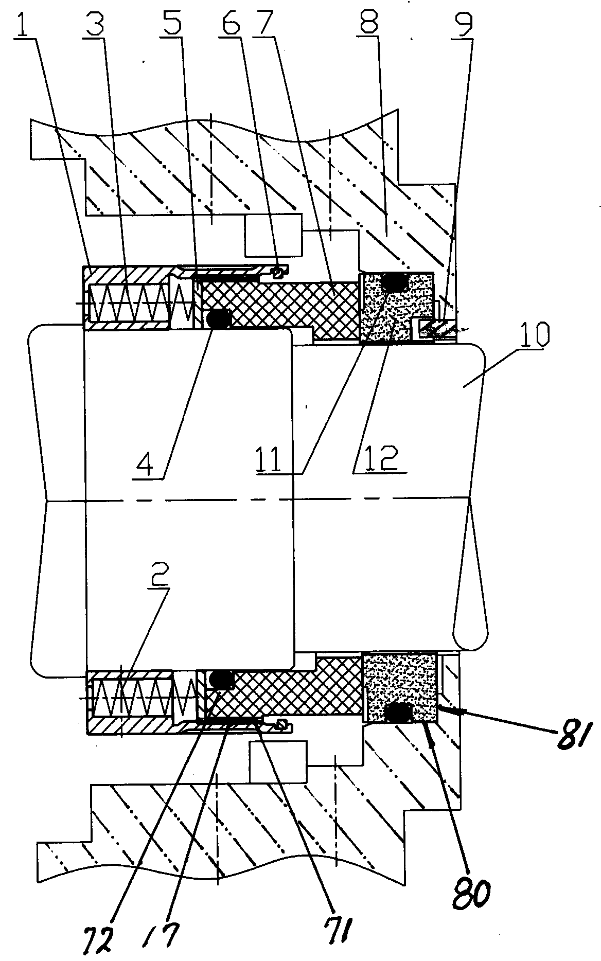
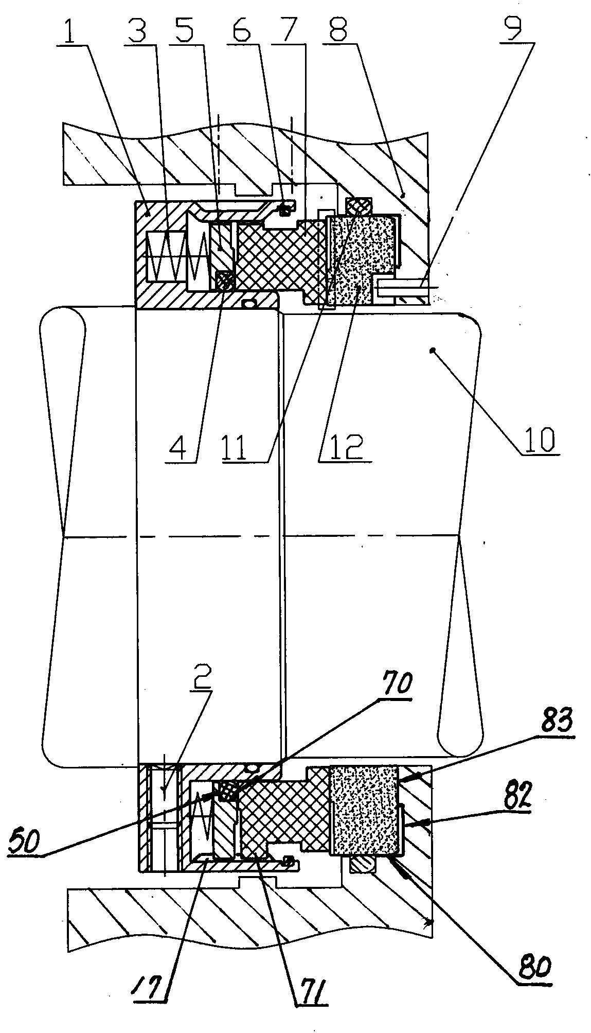
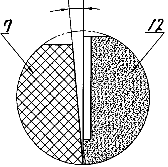
[0021]The present invention includes a spring box 1, a set screw 2, a compensation spring 3, a sliding sealing ring 4, a push ring 5, a snap ring 6, a moving ring assembly composed of a moving ring 7, a static ring 12, an anti-rotation pin 9, and a static ring The static ring assembly composed of the auxiliary sealing ring 11 and the gland 8, the moving ring assembly is installed on the shaft 10 or the bushing, the moving ring compensation spring 3 is installed in the spring seat hole in the spring box 1 and acts on the moving ring through the push ring 5 7. On the rear end surface, a plurality of convex grooves 71 are evenly distributed on the outer circle of the rear end of the moving ring 7 to cooperate with the groove 17 provided on the inner hole of the front edge of the spring box 1 to prevent the moving ring 7 from rotating relative to the spring box 1. The inner aperture of the leading edge of the spring box 1 is provided with a circlip 6 to cooperate with the front end...


PUM


Abstract

The invention discloses a mechanical dry gas sealing device for pumps. The mechanical dry gas sealing device comprises a movable ring component and a fixed ring component, wherein the movable ring component comprises a spring box (1), a stopper screw (2), a spring (3), a sealing ring (4), a pushing ring (5), a snap spring (6) and a movable ring (7), and the fixed ring component comprises a fixed ring (12), an anti-rotating pin (9), a sealing ring (11) and a gland (8). The mechanical dry gas sealing device is characterized in that the sliding sealing ring (4) is mounted in a seam allowance groove (50) on the inner diameter of the front end of the pushing ring (5), the pushing ring (5) is in close fit with the rear end face (70) of the movable ring (7), and compression rate of the O-shaped sliding sealing ring (4) ranges from 2% to 5%. A sealing end face of the movable ring (7) of a compensation ring is a conical surface. A boss (83) is arranged on the inner diameter of a vertical end face (82) mounting a seam allowance groove (80) of the fixed ring (12) and is matched with the inner diameter of the inner end face of the fixed ring (12) in a support manner. An end face of the compensation ring of the mechanical dry gas sealing device is good in adherence. Besides, the mechanical dry gas sealing device is stable to run, high in interference resistance, good in sealing performance and suitable for diversified working conditions.

Description

technical field [0001] The invention relates to a mechanical seal device, in particular to a dry gas mechanical seal device for a pump. [0002] The dry gas mechanical seal (Dry Gas Seal) device is a non-contact mechanical seal that relies on gas film lubrication. When the seal is working, the sealing gas is introduced through the dynamic pressure groove opened on the sealing end surface, so that the two sealing end surfaces are separated by a stable thin gas film (2-10μm) and are in a non-contact operating state, so the sealing friction The auxiliary material is basically not limited by the PV value, and is especially suitable as a shaft seal for high-speed and high-pressure equipment. Background technique [0003] The mechanical seal device is a device for preventing fluid leakage composed of at least one pair of end faces perpendicular to the axis of rotation, which are kept in contact with each other under the action of fluid pressure and the elastic force or magnetic f...

Claims


Application Information

Patent Timeline
Patent Type & Authority Applications(China)
IPC IPC(8): F16J15/16F16J15/34
Inventor 刘永生刘斌
Owner DANDONG COLOSSUS GROUP
Why Eureka
Try Eureka