Refrigerant flow control method and device for multi-connected air conditioning system

A multi-connected air conditioner and refrigerant flow technology, which is applied in space heating and ventilation, heating and ventilation control systems, heating and ventilation safety systems, etc., can solve the waste of energy consumption of indoor units, poor heating effect of indoor mechanisms, and electronic expansion valves The opening has not been effectively adjusted to achieve the effect of ensuring the heating effect and avoiding waste of energy consumption

Active Publication Date: 2014-01-01
QINGDAO HISENSE HITACHI AIR CONDITIONING SYST
View PDF3 Cites 50 Cited by
  • Summary
  • Abstract
  • Description
  • Claims
  • Application Information

AI Technical Summary

Problems solved by technology

[0005] The inventors of the present invention found that this technical solution only adjusts the opening of the electronic expansion valves of the indoor units with the most refrigerant and the least refrigerant, but the open...

Method used


Image

  • Refrigerant flow control method and device for multi-connected air conditioning system
  • Refrigerant flow control method and device for multi-connected air conditioning system
  • Refrigerant flow control method and device for multi-connected air conditioning system

Examples


Embodiment 1

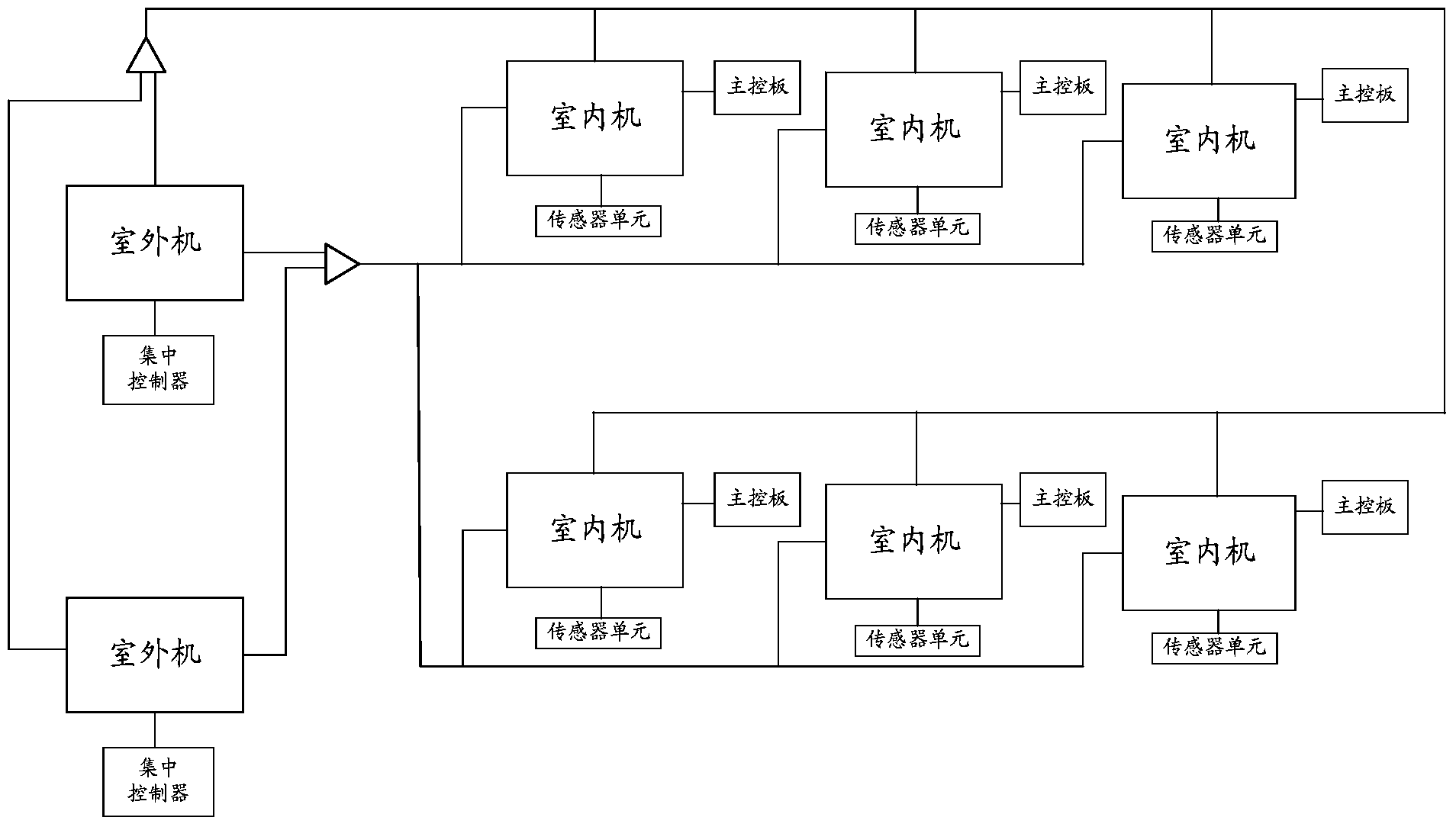
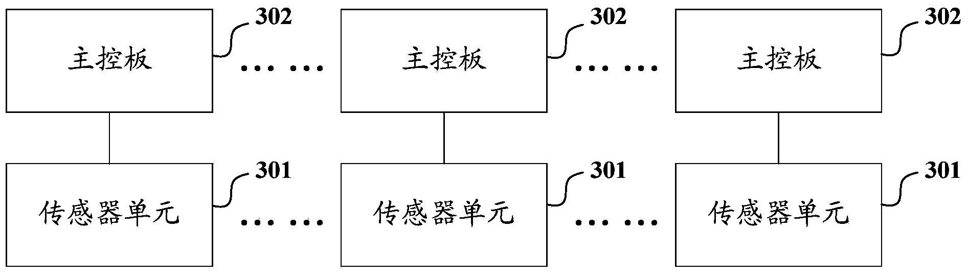
[0028] The structure of the refrigerant flow control device of the multi-connected air-conditioning system provided by Embodiment 1 of the present invention is as follows: image 3 As shown, the device includes: a control module for each indoor unit in the multi-connected air-conditioning system; the control module of one indoor unit specifically includes: a sensor unit 301 and a main control board 302; wherein,

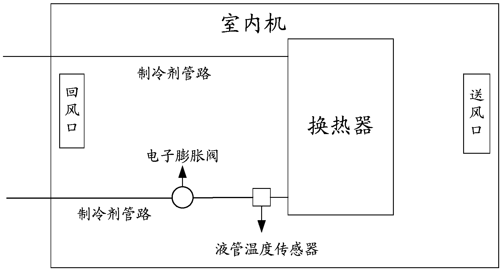
[0029] The sensor unit 301 includes: a high-pressure pressure sensor set on the refrigerant pipeline connected to the exhaust port of the outdoor unit compressor corresponding to the indoor unit, a return air temperature sensor set at the return air port of the indoor unit, and a return air temperature sensor set at the air return port of the indoor unit. The air supply temperature sensor of the tuyere, the liquid pipe temperature sensor arranged on the refrigerant pipeline connected to the outlet of the heat exchanger of the indoor unit; wherein,

[0030] The high-pre...

Embodiment 2

[0081] The structure of the refrigerant flow control device of the multi-connected air-conditioning system provided by Embodiment 2 of the present invention is as follows: Figure 5As shown, the device includes: a control module for each indoor unit in the system, and a centralized controller for the outdoor units in the system; the control module of one of the indoor units specifically includes:

[0082] The sensor unit 501 includes: a high-pressure pressure sensor set on the refrigerant pipeline connected to the exhaust port of the outdoor unit compressor in the unit where the indoor unit is located, a return air temperature sensor set at the return air port of the indoor unit, and a return air temperature sensor set at the air return port of the indoor unit. The air supply temperature sensor of the air supply port of the indoor unit, and the liquid pipe temperature sensor arranged on the refrigerant pipeline connected to the heat exchanger outlet of the indoor unit; wherein,...


PUM


Abstract

The invention discloses a refrigerant flow control method and device for a multi-connected air conditioning system. The device comprises control modules; each control module is provided for each indoor unit of the multi-connected air conditioning system. Each control module for the corresponding indoor unit comprises a sensor unit and a master control panel; the sensor unit used for acquiring data of the indoor unit comprises a high pressure sensor, a return air temperature sensor, a supply air temperature sensor and a liquid pipe temperature sensor; the master control board is used for receiving user-set temperature and acquiring data from the sensor unit to calculate target supercooling degree and actual supercooling degree when each sampling period is up; a difference between the actual supercooling degree and the target supercooling degree is used as a supercooling degree difference; an opening signal of an electronic expansion valve is adjusted to control opening of the electronic expansion valve of the corresponding indoor unit according to a difference between the supercooling degree difference of the current sampling period and the supercooling degree difference of previous sampling period. Through the use of the refrigerant flow control method and device, heating effect of each indoor unit can be guaranteed and energy consumption can be avoided.

Description

technical field [0001] The invention relates to a multi-connected air conditioner control technology, in particular to a refrigerant flow control method and device for a multi-connected air conditioner system. Background technique [0002] With the continuous expansion of the scale of integrated buildings and the continuous improvement of users' requirements for the comfort of the indoor environment, the multi-connected air-conditioning system is becoming larger and larger, and the number of indoor units towed by each outdoor unit is large. The distances between the outdoor units are different. When the system is running in heating mode, in order to avoid the refrigerant bias flow and ensure the effective subcooling of the refrigerant, the existing technology mainly takes the subcooling degree at the outlet of the heat exchanger of each indoor unit as the control target. If the control If the target exceeds the threshold, the opening of the electronic expansion valve of the ...

Claims


Application Information

Patent Timeline
IPC IPC(8): F24F11/00F24F11/02
Inventor 宋敏李丛来游少芳卢广宇王战术
Owner QINGDAO HISENSE HITACHI AIR CONDITIONING SYST
Why Eureka
Try Eureka