Oil return control system based on shell-and-tube heat exchanger

A shell-and-tube heat exchanger and oil return control technology, which is used in refrigerators, refrigeration components, refrigeration and liquefaction, etc. problem, to achieve the effect of improving oil return efficiency

Active Publication Date: 2014-01-01
QINGDAO HISENSE HITACHI AIR CONDITIONING SYST
View PDF6 Cites 5 Cited by
  • Summary
  • Abstract
  • Description
  • Claims
  • Application Information

AI Technical Summary

Problems solved by technology

In this way, on the one hand, the lubricating oil cannot be circulated back to the compressor, causing wear between the internal components of the compressor, affecting the life and reliability of the compressor, and reducing the reliability of the cooling operation of the heat pump air conditioner; on the other hand, A large amount of lubricating oil is deposited on the bottom of the cylinder 01, which will reduce the contact area between the refrigerant and the spiral water pipe, occupy the space required for the refrigerant to evaporate, reduce the heat transfer efficiency of the heat pump air conditioner, and cause the cooling performance to decay
[0007] In order to reduce the deposition of lubricating oil at the bottom of the shell-and-tube heat exchanger, an improved technical solution is proposed in the prior art. An oil return hole is provided at the bottom of the shell-and-tube heat exchanger for oil return, but due to the In this mode, the outlet pipe, water inlet pipe, refrigerant air pipe and refrigerant liquid pipe are opened at the same time, the pressure difference between the inlet and outlet of cylinder 01 is small, and the lubricating oil can only return to oil through gravity, and the oil return efficiency is low

Method used


Image

  • Oil return control system based on shell-and-tube heat exchanger
  • Oil return control system based on shell-and-tube heat exchanger
  • Oil return control system based on shell-and-tube heat exchanger

Examples


Embodiment Construction

[0053] The technical solutions of the various embodiments of the present invention will be clearly and completely described below in conjunction with the accompanying drawings. Apparently, the described embodiments are only some of the embodiments of the present invention, not all of them. Based on the embodiments of the present invention, all other embodiments obtained by persons of ordinary skill in the art without making creative efforts belong to the protection scope of the present invention.

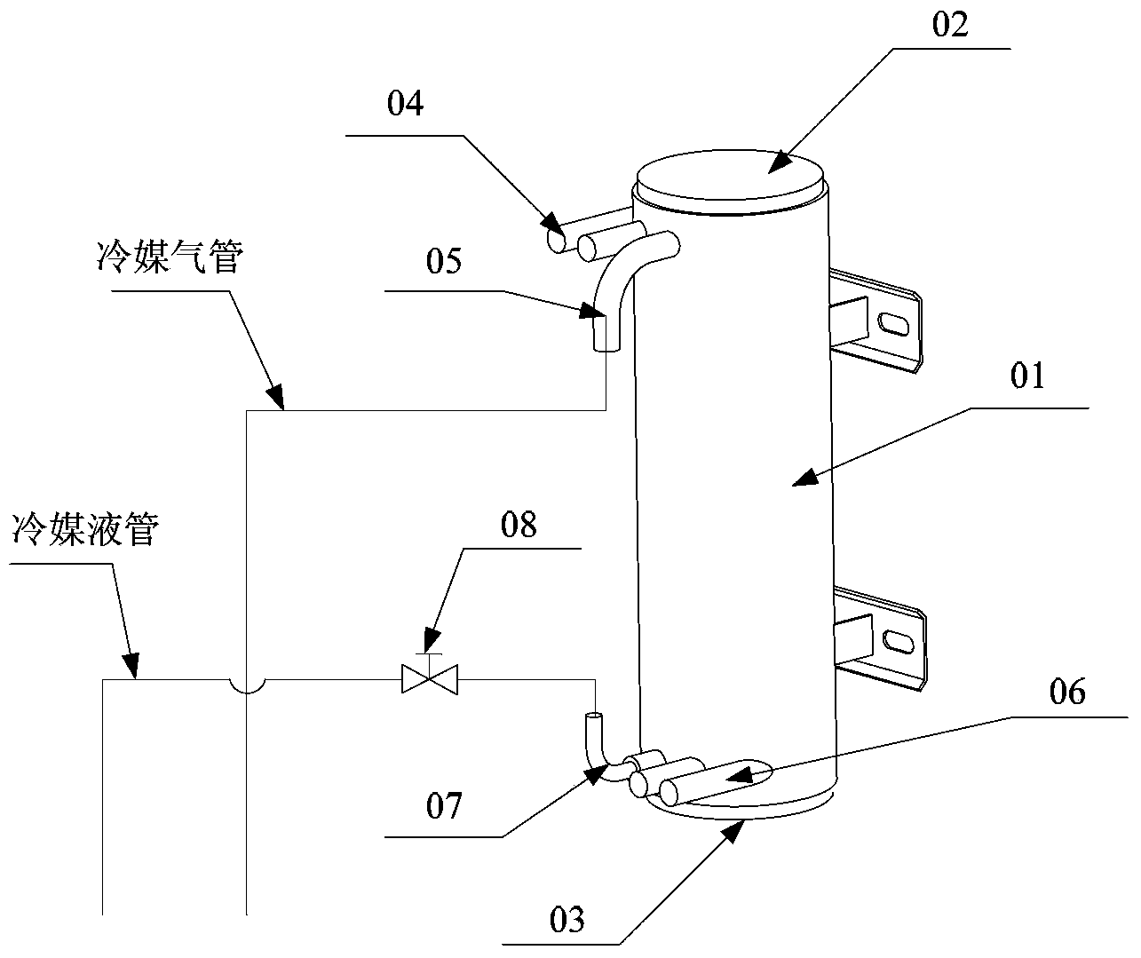
[0054] Currently, oil return is performed by setting an oil return hole at the bottom of the shell-and-tube heat exchanger. Although the deposition of lubricating oil at the bottom of the shell-and-tube heat exchanger can be reduced, due to the fact that the existing shell-and-tube heat exchanger is cooling In this mode, the outlet pipe, water inlet pipe, refrigerant gas pipe and refrigerant liquid pipe are opened at the same time, the pressure difference between the inlet and outlet...


PUM


Abstract

The invention discloses an oil return control system based on a shell-and-tube heat exchanger. The oil return control system comprises a barrel, an oil chamber, a first solenoid valve, a second solenoid valve and a third solenoid valve, wherein the oil chamber is used for containing lubricating oil flowing from the bottom of the barrel; the first solenoid valve is used for controlling the pressure of the inner cavity of the oil chamber; the second solenoid valve is used for discharging the lubricating oil in the oil chamber into a refrigerant air pipe; the third solenoid valve is used for discharging the lubricating oil deposited on the bottom of the barrel into the oil chamber; the oil chamber is arranged below the bottom of the barrel; one end of the third solenoid valve is connected with a solenoid valve pipe orifice which is communicated with the inner cavity of the barrel and is formed in the side wall of the lower part of the barrel; the other end of the third solenoid valve is connected with a first pipe orifice formed in the side wall of the oil chamber; one end of the first solenoid valve is connected with a second pipe orifice formed in the bottom of the oil chamber; the other end of the first solenoid valve is connected with a refrigerant liquid pipe orifice formed in the side wall of the lower part of the barrel; one end of the second solenoid valve is connected with the first pipe orifice formed in the bottom of the oil chamber; the other end of the second solenoid valve is connected with a refrigerant air pipe orifice formed in the side wall of the upper part of the barrel. By using the oil return control system based on the shell-and-tube heat exchanger, the oil return efficiency is improved.

Description

technical field [0001] The invention relates to the technical field of air source heat pumps, in particular to an oil return control system based on a shell-and-tube heat exchanger. Background technique [0002] Air source heat pump technology is an energy-saving and environmentally friendly heating technology based on the reverse Carnot cycle principle, and is widely used in heat pump air-conditioning systems. The heat pump air conditioning system obtains a low-temperature heat source through natural energy (air heat storage), and becomes a high-temperature heat source after efficient heat collection and integration, which is used for heating or hot water supply, and passes the refrigerant compressed by the compressor through the shell with water as the heat carrier Type heat exchanger to achieve heat exchange, realize the cooling and heating functions of the heat pump air conditioning system, the heat collection efficiency of the entire heat pump air conditioning system is...

Claims


Application Information

Patent Timeline
Patent Type & Authority Applications(China)
IPC IPC(8): F25B39/00
Inventor 耿海兵李虎马启成王远鹏游少芳蒋茂灿
Owner QINGDAO HISENSE HITACHI AIR CONDITIONING SYST
Why Eureka
Try Eureka