Hot air circulation system for I-phase drying air distribution of SCR (selective catalytic reduction) denitrated catalyst

A denitrification catalyst and circulation system technology, applied in the field of air purification equipment vent structure, can solve the problems of fast catalyst drying speed, slow drying speed, cracking of dried products, etc.

Active Publication Date: 2014-01-01
无锡华光新动力环保科技股份有限公司
View PDF6 Cites 1 Cited by
  • Summary
  • Abstract
  • Description
  • Claims
  • Application Information

AI Technical Summary

Problems solved by technology

The disadvantages of this device are: the distribution of the return air outlet is uneven, although the lower edge of the door of the drying room is sealed with thermal insulation cotton, it still cannot be completely sealed. After dehumidification, when there is negative pressure in the drying room, the Air leakage in the drying room is caused. At this time, there is air circulation between the lower edge of the door and the outside, resulting in uneven temperature and humidity in the drying room. The drying speed of the catalyst near the door is relatively fast, and the drying speed of the other end opposite to the door is slow, resulting in I The drying period of the section is too long, which even leads to cracking of the dried product, which is a technical problem that has plagued the catalyst industry for a long time

Method used


Image

  • Hot air circulation system for I-phase drying air distribution of SCR (selective catalytic reduction) denitrated catalyst
  • Hot air circulation system for I-phase drying air distribution of SCR (selective catalytic reduction) denitrated catalyst

Examples


Embodiment Construction

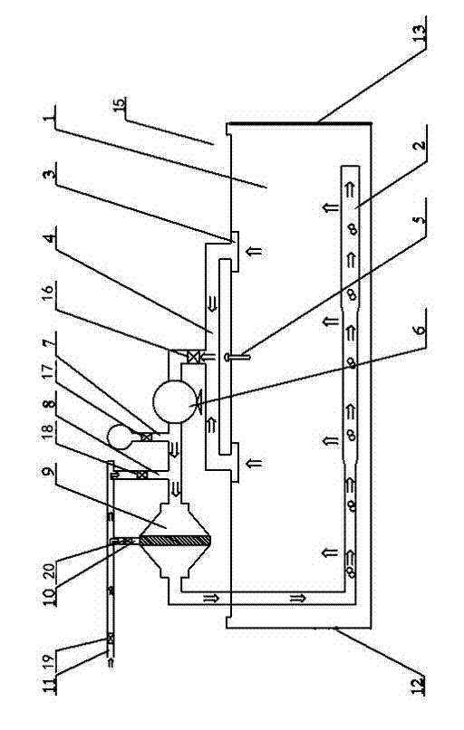
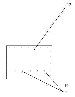
[0019] See figure 1 , figure 2 , which includes a drying chamber 15, a heat exchanger 9, and a circulating fan 6. The drying chamber includes two end walls, side walls, and a cavity 1 surrounded by both end walls and side walls. The hot air duct 2 is arranged in the cavity 1 One of the two end walls is an openable drying chamber door 13 , the other end has a through hole 14 under the end wall 12 , and the inside of the hole 14 communicates with the cavity 12 . The small holes 14 are specifically circular small holes; the small holes 14 are horizontally arranged in a single row; the hot air duct 2 is located below the cavity 1, and hot air outlets are evenly arranged on the hot air duct 2, and the upper ends of the cavity 1 Each is provided with return air outlet 3, and return air outlet 3 is connected with return air duct 4, and return air duct 4, heat exchanger 6, circulation blower 6 are positioned at the outside of drying chamber 15, and the outlet of return air duct 4 is...


PUM


Abstract

The invention provides a hot air circulation system for I-phase drying air distribution of SCR denitrated catalyst. The hot air circulation system for the I-phase drying air distribution of the SCR denitrated catalyst enables the inner temperature and humidity of a drying chamber to be uniform, enables the sample drying velocity before and behind the chamber to be uniform, shortens the I-phase drying period and ensures no cracking of dried products. The hot air circulation system comprises the drying chamber, a heat exchanger and a circulation fan, wherein the drying chamber comprises two end walls, two side walls and a cavity enclosed by the two end walls and the two side walls, hot air vents are distributed inside the cavity, and one ends of the two end walls are provided with an openable drying chamber door. The hot air circulation system for the I-phase drying air distribution of the SCR denitrated catalyst is characterized in that penetrated small holes are formed in the lower portions of the other ends of the end walls, and the insides of the small holes are communicated with the cavity.

Description

technical field [0001] The invention relates to the technical field of the vent structure of air purification equipment, in particular to a hot air circulation system for drying and distributing air in the first stage of an SCR denitrification catalyst. Background technique [0002] In recent years, the control of nitrogen oxides has always been an urgent objective requirement for national economic sustainable development and environmental protection. Among its control technologies, selective catalytic reduction (NH 3 -SCR) technology occupies a mainstream position due to its maturity and reliability. [0003] The molding process of SCR denitration catalyst mainly includes mixing, extrusion, drying, roasting and other steps, all of which have an important impact on the molding of SCR denitration catalyst. Among them, the wet catalyst after extrusion needs to be dried. During the drying process, the catalyst will shrink in the outer diameter and length direction due to w...

Claims


Application Information

Patent Timeline
Patent Type & Authority Applications(China)
IPC IPC(8): F26B21/02
Inventor 陈斌陈玲孟德海尤毓敏高宽峰孙志翱
Owner 无锡华光新动力环保科技股份有限公司
Why Eureka
Try Eureka