Energy-saving fresh air system for clean room

A technology of fresh air system and clean room, which is applied in the field of energy-saving fresh air system for clean room, can solve the problems of unreasonable design in the early stage, increase of capital consumption and high cost of clean room fresh air system operation.

Inactive Publication Date: 2019-02-05
艾尔科建设工程(江苏)有限公司
View PDF4 Cites 2 Cited by
  • Summary
  • Abstract
  • Description
  • Claims
  • Application Information

AI Technical Summary

Problems solved by technology

Although the unidirectional flow clean room can achieve a high degree of cleanliness, the cost is high and the construction and maintenance costs of the unidirectional flow clean room are relatively high. Room requirements, whether it is from the construction of the fresh air system of the clean room or the capital investment in the operation process, the capital investment of the turbulent flow

Method used


Image

  • Energy-saving fresh air system for clean room

Examples


specific Embodiment example 1

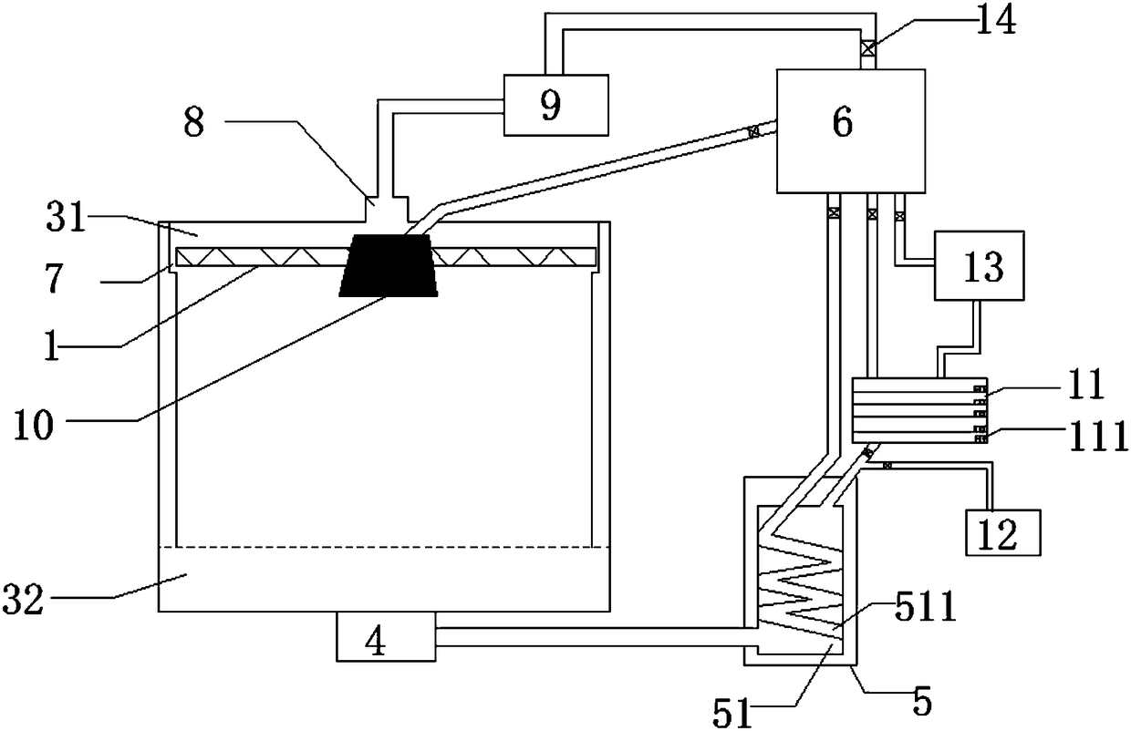
[0019] An energy-saving fresh air system for a clean room, comprising: a top plate 1 and an air-leakage bottom plate 2 are respectively installed under the top wall and above the bottom wall of the clean room; 2 and the bottom wall form the return air main passage 32, the side wall of the clean room around the top plate 1 is provided with a return air outlet 7 and the return air outlet 7 communicates with the return air secondary passage 31, and the center of the clean room bottom wall is connected to the return air main passage 32 connected return air unit 4 sucks the gas with high dust content at the bottom of the clean room through the air leakage bottom plate 2 into the return air main channel 32. The heat exchange channel 51 is provided with a spiral heat exchange tube 511, and the spiral heat exchange tube 511 accounts for 4 / 5 of the cross-sectional area of ​​the heat exchange channel 51, and the inlet end of the heat exchange channel 51 is connected to the air outlet of ...

specific Embodiment 2

[0024] An energy-saving fresh air system for a clean room, comprising: a top plate 1 and an air-leakage bottom plate 2 are respectively installed under the top wall and above the bottom wall of the clean room; 2 and the bottom wall form the return air main passage 32, the side wall of the clean room around the top plate 1 is provided with a return air outlet 7 and the return air outlet 7 communicates with the return air secondary passage 31, and the center of the clean room bottom wall is connected to the return air main passage 32 connected return air unit 4 sucks the gas with high dust content at the bottom of the clean room through the air leakage bottom plate 2 into the return air main channel 32. The heat exchange channel 51 is provided with a spiral heat exchange tube 511, the spiral heat exchange tube 511 accounts for 2 / 3 of the cross-sectional area of ​​the heat exchange channel 51, and the inlet end of the heat exchange channel 51 is connected to the air outlet of the ...


PUM


Abstract

The invention discloses an energy-saving fresh air system for a clean room. The fresh air system comprises three air flues, the first air flue comprises fresh air subjected to heat exchanging with return air in an air return main channel, the second air flue comprises return air exhausted from a return air auxiliary channel and filtered through a first filter unit, and the third air flue comprisesreturn air entering a multi-stage filter unit from the return air main channel to be purified. When air exhausted out of the return air main channel is low in cleanliness degree, high in filter costor incapable of being purified to the needed cleanliness, return air waste can be directly exhausted to an air treatment chamber. Due to design of the fresh air system, the fresh air need amount in the clean room can be greatly reduced, and the energy consumption of the fresh air unit can be greatly reduced.

Description

technical field [0001] The invention relates to the technical field of clean room fresh air, in particular to an energy-saving fresh air system for a clean room. Background technique [0002] Cleanroom technology (cleanroom) is a new technology born to meet the requirements of precision, miniaturization, high purity, high quality and high reliability of experimental research and product processing. Clean rooms are mostly used in precision and high-precision quality requirements such as microelectronics, biopharmaceuticals, surgical treatment, and precision instrument manufacturing. Therefore, clean workshops have high requirements for air temperature, humidity, and cleanliness. Although the unidirectional flow clean room can achieve a high degree of cleanliness, the cost is high and the construction and maintenance costs of the unidirectional flow clean room are relatively high. Whether it is from the construction of the fresh air system of the clean room or the capital inv...

Claims


Application Information

Patent Timeline
IPC IPC(8): F24F1/0073F24F13/02F24F13/30F24F13/28
CPCF24F1/0007F24F13/02F24F13/28F24F13/30F24F3/167F24F8/20
Inventor 毛海军
Owner 艾尔科建设工程(江苏)有限公司
Why Eureka
Try Eureka