Rapid Direct-current deicing short circuit device of electric transmission line

A technology for DC ice melting and power transmission lines, which is applied in the installation of cables, electrical components, overhead installation, etc. It can solve the problems of time-consuming and inability to guarantee the personal safety of operators, and achieves simple structure, convenient connection of adjacent phases, and fast wiring Effect

Active Publication Date: 2014-01-01
郴州市东晟科技有限公司
View PDF6 Cites 13 Cited by
  • Summary
  • Abstract
  • Description
  • Claims
  • Application Information

AI Technical Summary

Problems solved by technology

Therefore, it takes a lot of time to collect, release and fix the short-circuit cable, and to climb the tower re

Method used


Image

  • Rapid Direct-current deicing short circuit device of electric transmission line
  • Rapid Direct-current deicing short circuit device of electric transmission line
  • Rapid Direct-current deicing short circuit device of electric transmission line

Examples


Embodiment Construction

[0024] The present invention will be described in further detail below in conjunction with the accompanying drawings and embodiments, but these embodiments should not be construed as limiting the present invention.

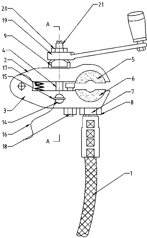
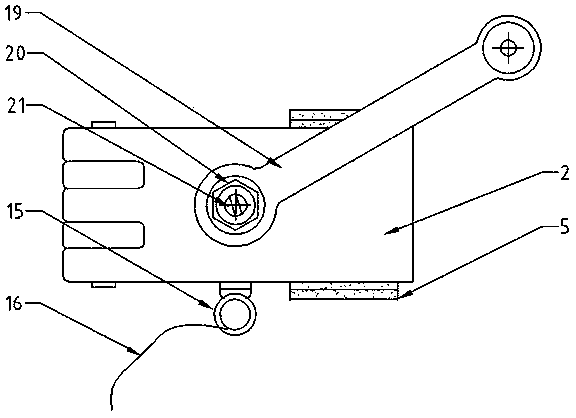
[0025] Such as figure 1 , 2 As shown, this embodiment provides a DC deicing quick short-circuit device for power transmission lines, which includes a short-circuit cable 1, and two ends of the short-circuit cable 1 are respectively connected with a wire hook clip, and the wire hook clip includes an upper clamp block 2. The lower clamping block 3 and the pull rod 4; it is characterized in that: one end of the upper clamping block 2 and the lower clamping block 3 is flexibly connected by a hinge, and the opposite clamping surface of the other end is respectively provided with upper and lower clamping dies; The upper half-tile combined beryllium-copper bushing 5 and the lower half-watt combined beryllium-copper bushing 6 matching the diameter of the overhead line ar...


PUM


Abstract

The invention relates to a rapid direct-current deicing short circuit device of an electric transmission line and belongs to the technical field of electric power line device fittings. According to the structure, the rapid direct-current deicing short circuit device of the electric transmission line comprises a short circuit cable (1). The two ends of the short circuit cable (1) are respectively connected with one line hanging connection clamp. One end of an upper clamping block (2) of each line hanging connection clamp and one end of a lower clamping block (3) of the line hanging connection clamp are movably connected through a hinge, the other end of each upper clamping block (2) is provided with an upper semi-tile combined beryllium copper sleeve (5), and the other end of each lower clamping block (3) is provided with a lower semi-tile combined beryllium copper sleeve (6), wherein the upper semi-tile combined beryllium copper sleeve (5) and the lower semi-tile combined beryllium copper sleeve (6) are matched with the overhead line in diameter. The two ends of the short circuit cable (1) are respectively connected with a downward-convex conductive block (7) in a rapid screwing mode through an internal-thread clamping connector (8). The lower end of each pull rod (4) is square and is connected with the middle of one lower clamping block (3) through a shotpin mechanism. According to the rapid direct-current deicing short circuit device of the electric transmission line, the line hanging connection clamps are connected to two overhead lines which are erected in parallel, a large current power source is loaded between adjacent phases of the overhead lines, heat generated through a resistor of the overhead aluminum conductors is utilized, so that attached ice is rapidly deiced and eliminated, and adjacent phase connection can be rapidly and conveniently conducted. The rapid direct-current deicing short circuit device of the electric transmission line has the advantages of being capable of saving labor, short in time, rapid in installation, convenient to install, and firm.

Description

technical field [0001] The invention relates to the technical field of high-voltage transmission line deicing, in particular to a fast short-circuit device for direct current melting ice of a transmission line, which belongs to the technical field of power line equipment and fittings. Background technique [0002] The weather is cold in winter, and the transmission line is easy to wrap a thick layer of ice. The ice layer increases the weight of the overhead line, and it is easy to generate resonance under the action of the wind, which has a very serious impact on the power tower, thereby affecting the entire power supply system. Threats to our lives and our economy. [0003] The current method of melting ice is mostly DC short-circuit ice melting, which requires the staff to lift the short-circuit cable for high-altitude installation. When performing short-circuit, it is necessary to install and disassemble the connection of multi-strand short-circuit cables and overhead lin...

Claims


Application Information

Patent Timeline
IPC IPC(8): H02G7/16
Inventor 谭珍忠粟立祥周文胜戴艳平
Owner 郴州市东晟科技有限公司
Why Eureka
Try Eureka