Current limiting circuit

A current limiting and circuit technology, applied in circuit devices, emergency protection circuit devices for limiting overcurrent/overvoltage, emergency protection circuit devices, etc. and other problems to avoid malfunction

Active Publication Date: 2014-01-01
WUXI ZGMICRO ELECTRONICS CO LTD
View PDF5 Cites 7 Cited by
  • Summary
  • Abstract
  • Description
  • Claims
  • Application Information

AI Technical Summary

Problems solved by technology

[0003] However, in the actual system, sometimes the instantaneous current is too large, but the duration is not long. For example, when the radio frequency circuit is transmitting, a high instantaneous current is required.
The existing current limiting circuit will have overcurrent protection, resulting in a drop in output voltage. When the output voltage drops sharply, some circuits will not work properly.

Method used


Image

  • Current limiting circuit
  • Current limiting circuit
  • Current limiting circuit

Examples


Embodiment Construction

[0021] The embodiment of the present invention provides a current limiting circuit, which is suitable for current limiting protection circuits of various power management chips, such as low dropout voltage regulators or DC-DC converters, etc. At the same time, it can realize the higher threshold current limiting protection under the transient response of the circuit, which can support the system application that requires a larger current output in an instant, and avoid the system malfunction due to the limitation of the instantaneous large current.

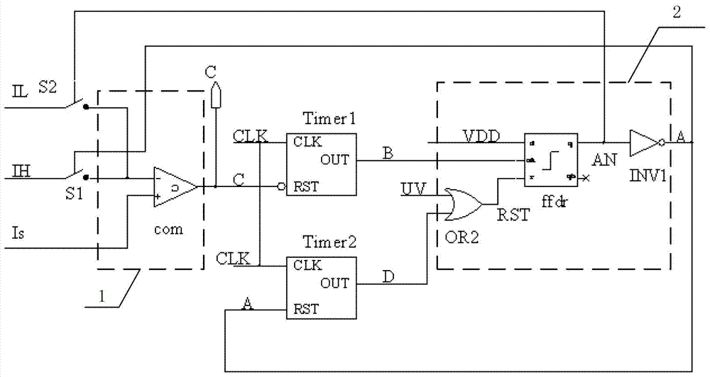
[0022] figure 1 A circuit diagram of a current limiting circuit provided by an embodiment of the present invention. Such as figure 1 As shown, the current limiting circuit includes: a comparison unit 1 , a first counter Timer1 , a flip-flop unit 2 and a second counter Timer2 .

[0023] The comparison signals input by the comparison unit 1 are respectively a reference current signal and a sampling current signal. By comparing th...


PUM


Abstract

The invention relates to a current limiting circuit. The current limiting circuit comprises a comparing unit, a trigger unit, a first counter and a second counter. The comparing unit is used for comparing reference current and sampling current so as to obtain overcurrent judgment signals and control current of an external circuit always not to exceed the reference current when overcurrent happens to the sampling current, and the reference current is transient reference current or steady reference current. The trigger unit is used for determining that the reference current connected to the comparing unit is the transient reference current or the steady reference current. The first counter works when the sampling current is higher than the transient reference current, and the full time of the first counter is the overcurrent time allowing the sampling current to exceed the transient reference current. The second counter works when the sampling current is higher than the steady reference current, and the full time of the second counter is the overcurrent time allowing the sampling current to exceed the steady reference current.

Description

technical field [0001] The invention relates to the technical field of electronic circuits, in particular to a current limiting circuit. Background technique [0002] The current limiting circuit in a traditional power management chip generally has a fixed current threshold. For example, in a voltage regulator, the peak value of its output current is generally controlled to a certain current threshold, and its maximum output current is realized to a certain fixed value through negative feedback. The current limiting circuit is used to limit the power chip from being damaged when the load current is too large. The main damage mode of the semiconductor circuit in the event of overcurrent is thermal damage, that is, the chip is damaged when the chip is overheated. In the prior art, the control of the maximum average current is realized by setting a constant current peak value. [0003] But in the actual system, sometimes the instantaneous current is too large, but the durati...

Claims


Application Information

Patent Timeline
Patent Type & Authority Applications(China)
IPC IPC(8): H02H9/02
Inventor 王钊
Owner WUXI ZGMICRO ELECTRONICS CO LTD
Why Eureka
Try Eureka