Unlock instant, AI-driven research and patent intelligence for your innovation.

imaging device

An imaging device, pixel technology, applied in radiation control device, image communication, television and other directions, can solve the problem of no highlight

Active Publication Date: 2018-03-13
SONY SEMICON SOLUTIONS CORP
View PDF4 Cites 0 Cited by
  • Summary
  • Abstract
  • Description
  • Claims
  • Application Information

AI Technical Summary

Problems solved by technology

In such an imaging device, even when the difference between bright and dark of the subject image is large, highlights do not appear, and it is possible to generate an image signal with a high dynamic range

Method used


Image

  • imaging device
  • imaging device
  • imaging device

Examples


Embodiment

[0019] [Configuration Example of Embodiment of Imaging Device]

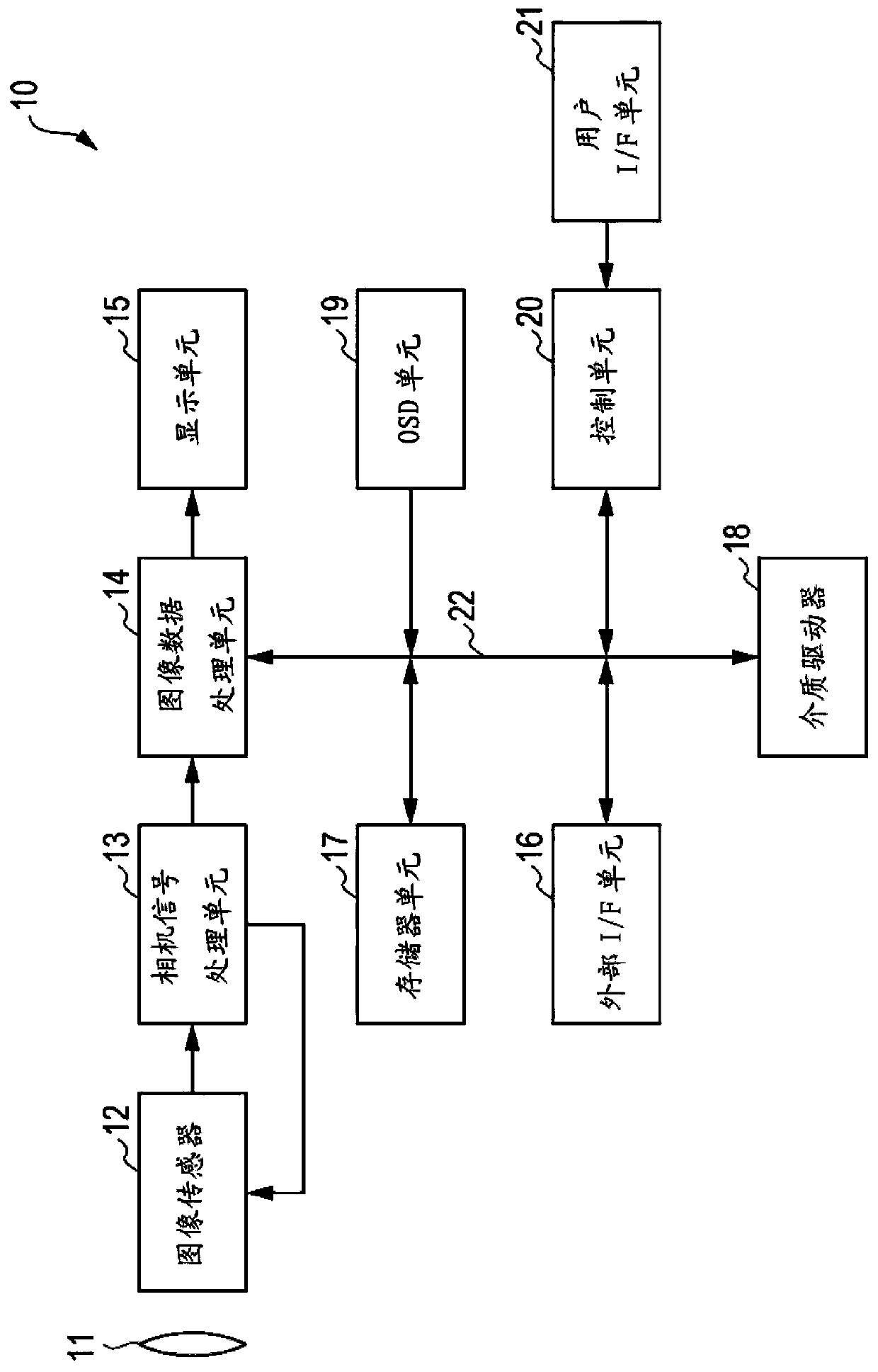
[0020] figure 1 is a block diagram illustrating a configuration example of an imaging device according to an embodiment of the present technology.

[0021] The imaging device 10 includes: an optical block 11, an image sensor 12, a camera signal processing unit 13, an image data processing unit 14, a display unit 15, an external interface (I / F) unit 16, a memory unit 17, a media drive 18, an OSD unit 19 and control unit 20. The control unit 20 is connected to a user interface (I / F) unit 21 .

[0022] In addition, the image data processing unit 14 , the external interface unit 16 , the memory unit 17 , the media drive 18 , the OSD unit 19 , and the control unit 20 are connected to each other via a bus 22 . The imaging device 10 captures an image of a subject, and displays the captured image on a display unit 15 or records image data in a media drive 18 .

[0023] Specifically, the optical block 11 of the imagin...


PUM


Abstract

The imaging device includes an image capture unit configured to capture an optical image of a corresponding one of the pixels included in the screen, and the image capture unit of a part of the pixels in the screen includes an adjustment unit including an electric field responsive material and configured for adjusting transmittance of light by the electric field responsive material; and a light receiving unit configured to receive light for which transmittance has been adjusted by the adjusting unit.

Description

technical field [0001] The present technology relates to an imaging device, and more particularly, to an imaging device that achieves reduced size while improving sensitivity and dynamic range of image capture by using an electric field responsive material. Background technique [0002] In recent years, improvements in sensitivity and dynamic range of image capture have been demanded along with miniaturization of pixels of image sensors. [0003] Therefore, an imaging device has been devised in which a liquid crystal panel capable of partially changing the transmittance of visible light is arranged in the preceding stage of a CCD (Charge Coupled Device) image sensor, and liquid crystal is performed based on an image signal output from the CCD image sensor. Feedback control of density of liquid crystals of the panel (for example, see Japanese Unexamined Patent Application Publication No. 2003-9007). In such an imaging device, even when the difference between bright and dark ...

Claims


Application Information

Patent Timeline
Patent Type & Authority Patents(China)
IPC IPC(8): H04N5/335H04N5/355H04N5/235H04N5/238G02F1/13H01L27/148H01L27/146
CPCH01L27/14627H01L27/14625H01L27/14621H04N23/741H04N23/75H04N25/133H04N25/135H04N25/00
Inventor 宋奇
Owner SONY SEMICON SOLUTIONS CORP