Real-time airway check status indicator

A technology of indicator and dynamic indication, used in tracheal intubation, bioelectrical signal measurement, medical science, etc.

Active Publication Date: 2014-01-01
KONINKLJIJKE PHILIPS NV
View PDF10 Cites 3 Cited by
  • Summary
  • Abstract
  • Description
  • Claims
  • Application Information

AI Technical Summary

Problems solved by technology

This delay, which can be as long as twenty seconds, can become longer in stressful emergency situations, such as handling a patient in the field who is not breathing and has gone into cardiac arrest

Method used


Image

  • Real-time airway check status indicator
  • Real-time airway check status indicator
  • Real-time airway check status indicator

Examples


Embodiment Construction

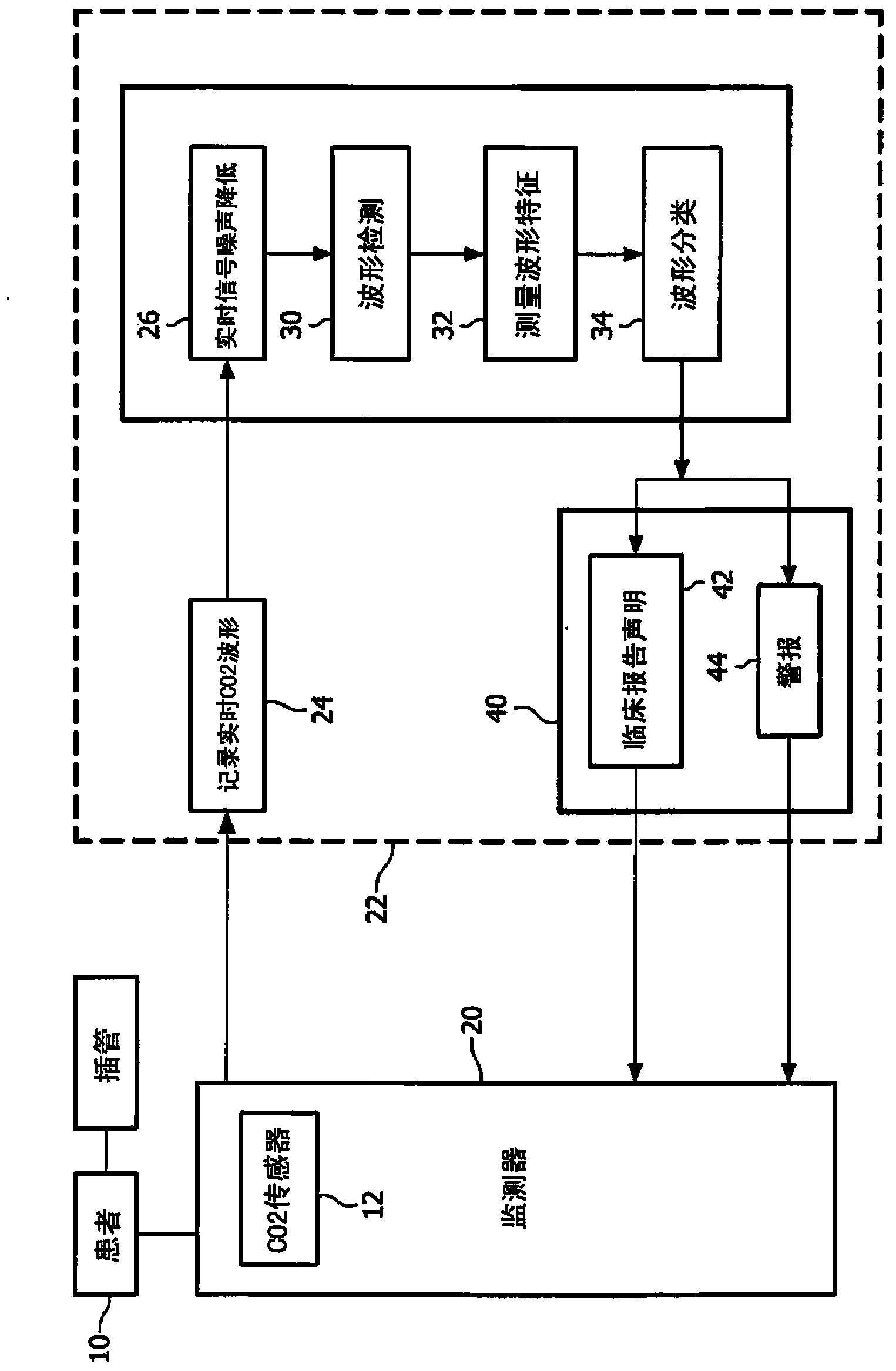
[0020] first reference figure 1 , shows a CO2 monitoring system 20 of the present invention in block diagram form, and the CO2 monitoring system 20 is used to monitor a patient 10 undergoing intubation. In a constructed embodiment, monitoring system 20 is incorporated into an MRx monitoring defibrillator. The patient's breathing gas is directed to the monitor's CO2 sensor 12, which senses the CO2 content of the patient's exhaled gas. The CO2 measurement signal from the sensor 12 is digitized into recorded digital samples as shown at 24 of the processing portion 22 of the monitor 20 . The CO2 digital samples are analyzed for noise content at 26 and the CO2 signal samples may also receive noise reduction. One technique for analyzing noise content is to analyze the high frequency content of a signal sample. A pure CO2 signal will show relatively little high frequency content. The noise level of the signal may be reduced by processing the signal at 26 of the monitoring section...


PUM


Abstract

Immediately after airway placement and / or following any patient transfer, an automated program may be activated in a CO2 monitoring device to provide an airway device placement check. The automated program needs time to determine if the airway placement has been successful or not. During analysis of CO2 respiration data by the program, real-time feedback is displayed to the user as soon as the airway check program is activated until the time that a final decision on the success of airway placement is made. The real-time feedback displays one or more indicators of the progress of the program toward a determination of a successful or failed placement.

Description

technical field [0001] The present invention relates to medical carbon dioxide (CO2) monitoring systems, and, in particular, to a CO2 monitoring system that provides a real-time indication of the success or failure of a patient's intubation. Background technique [0002] CO2 monitoring systems are commonly found in hospital operating rooms and intensive care units to monitor a patient's breathing. Typically, these systems are complex and large ventilation systems that monitor the patient's oxygen intake and respiratory CO2. However, there are other scenarios where CO2 monitoring is desired. One scenario is during intubation where air is provided to the patient by a manually operated breathing device. Another scenario is during the application of CPR to a patient suffering from cardiac arrest. In such cases, a portable unit such as the MRx Defibrillator Monitor produced by Philips Medical (Andover, MA) that can be used in a hospital, but is portable and capable of being ta...

Claims


Application Information

Patent Timeline
Patent Type & Authority Applications(China)
IPC IPC(8): A61B5/083A61M16/00
CPCA61B5/743A61M2230/432A61B5/0836A61B5/082A61M2230/06A61M2230/30A61M16/0051A61M2230/205A61B5/4848A61M16/04A61M2016/0413A61M16/021
Inventor S·巴巴埃萨德赫E·黑尔芬拜因S·H·周
Owner KONINKLJIJKE PHILIPS NV
Why Eureka
Try Eureka