
State estimation device

A technology for state estimation and measurement device, which is applied in measurement devices, instruments, complex mathematical operations, etc., and can solve problems such as estimating observation objects with high accuracy

Inactive Publication Date: 2014-01-01
TOYOTA JIDOSHA KK
View PDF5 Cites 2 Cited by
  • Summary
  • Abstract
  • Description
  • Claims
  • Application Information

AI Technical Summary

Problems solved by technology

[0006] However, in the conventional state estimation method using the Kalman filter, since the model for state estimation is fixed regardless of the time-to-time change of the state of the observed object, there is a problem that the state of the observed object cannot be estimated with high accuracy.

Method used


Image

  • State estimation device
  • State estimation device
  • State estimation device

Examples


no. 1 Embodiment approach ]

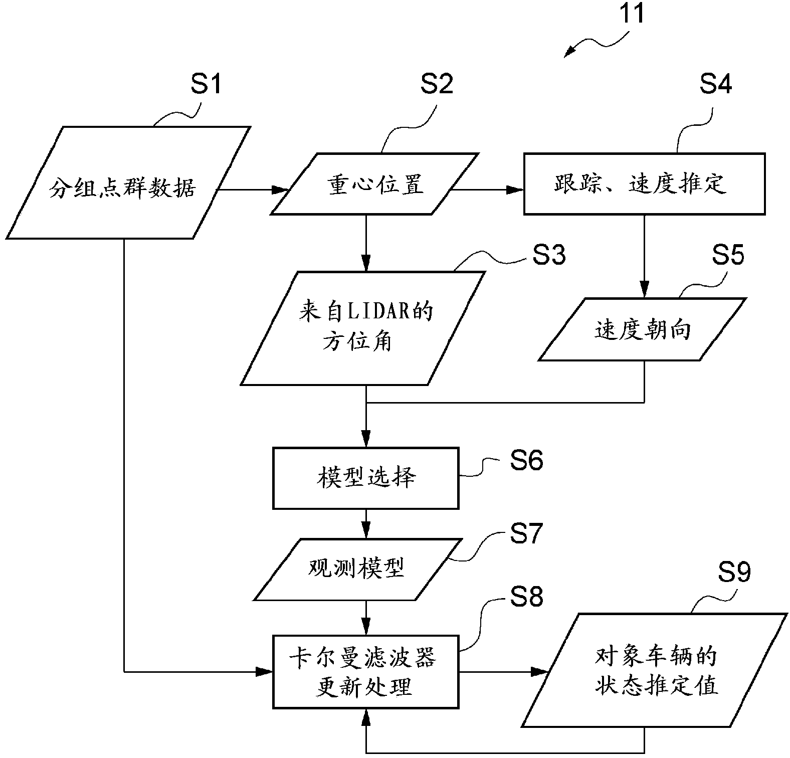
[0075] The estimation processing of the state estimation device 11 according to the first embodiment will be described. image 3 It is a figure which shows the estimation process of the state estimation apparatus concerning 1st Embodiment.

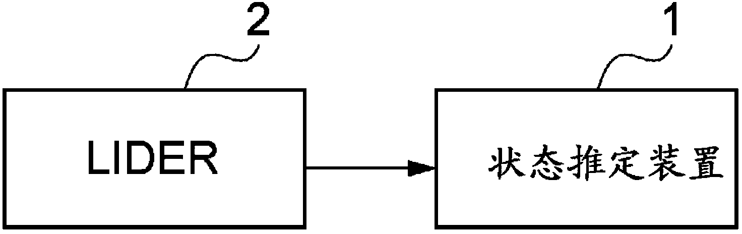
[0076] Such as image 3 As shown, the state estimation device 11 according to the first embodiment changes the observation model used in the Kalman filter update process based on the direction of the center position of the target vehicle with respect to the LIDAR 2 and the orientation of the target vehicle. As the observation model, there are the following eight: a rear observation model targeting the rear of the target vehicle, a left oblique rear observation model targeting the rear and left side of the target vehicle, a left observation model targeting the left side of the target vehicle, A left oblique front observation model for the front and left of the target vehicle, a front observation model for the front of the target vehicle, a...

no. 2 Embodiment approach ]

[0129] Next, the estimation processing of the state estimation device 12 according to the second embodiment will be described. The second embodiment is basically the same as the first embodiment, but differs from the first embodiment in the method of selecting an observation model. Therefore, only the parts different from the first embodiment will be described below, and the description of the same parts as the first embodiment will be omitted.

[0130] Figure 8 It is a figure which shows the estimation process of the state estimation apparatus concerning 2nd Embodiment. Such as Figure 8 As shown, the state estimation device 12 according to the second embodiment selects the observation models used in the current estimation process based on the observation models used in the previous estimation process.

[0131] Usually, the behavior change of the vehicle is continuous. Therefore, even if the positional relationship with the target vehicle or the state of the target vehic...

no. 3 Embodiment approach ]

[0138]Next, the estimation processing of the state estimation device 13 according to the third embodiment will be described. The third embodiment is basically the same as the first embodiment, but differs from the first embodiment in the method of selecting an observation model. Therefore, only differences from the first embodiment will be described below, and the description of the same parts as the first embodiment will be omitted.

[0139] Figure 9 It is a figure which shows the estimation process of the state estimation apparatus concerning 3rd Embodiment. As described above, in the first embodiment, the direction of the center position of the target vehicle with respect to LIDAR2 and the orientation of the target vehicle are obtained based on the grouped point cloud data generated in S1. In contrast, as Figure 9 As shown, in the third embodiment, the direction of the center position of the target vehicle with respect to LIDAR 2 and the orientation of the target vehic...


PUM


Abstract

The purpose of the present invention is to provide a state estimation device capable of estimating, with high accuracy, the state of an object to be observed. A state estimation device (1) estimates the state of a vehicle located in the periphery of the vehicle, to which the state estimation device (1) is mounted, by performing a Kalman filter updating process for computing the measurement data of a target vehicle obtained from a LIDAR (2), said Kalman filter updating process being performed by applying the aforementioned measurement data to a state estimation model. The state estimation device (1) changes the state estimation model used in the Kalman filter updating process on the basis of the state of the target vehicle or the positional relationship in relation to the target vehicle.

Description

technical field [0001] The present invention relates to an estimation device for estimating the state of an observation object by applying measurement data to a model for state estimation. Background technique [0002] Conventionally, a device described in Japanese Patent Application Laid-Open No. 2002-259966 is known as a technique for estimating the state of a dynamic observation object. The device described in Japanese Patent Application Laid-Open No. 2002-259966 includes a plurality of identification units, and realizes high precision estimation by switching identification methods according to predetermined conditions. [0003] Patent Document 1: Japanese Unexamined Patent Publication No. 2002-259966 [0004] However, even with the technique described in Japanese Patent Application Laid-Open No. 2002-259966, sufficient estimation accuracy cannot be obtained, and thus a higher-precision estimation method is required. [0005] In view of this, in recent years, a state es...

Claims


Application Information

Patent Timeline
Patent Type & Authority Applications(China)
IPC IPC(8): G01S17/66G01S17/93G08G1/16G01S17/931
CPCG01S17/936G08G1/165G06F17/18G08G1/16G08G1/166G01S17/66G01S17/931
Inventor 中村弘
Owner TOYOTA JIDOSHA KK
Learn More