
Edge alignment method

An edge alignment and edge technology, which is applied to machine tools, image data processing, and stone processing equipment suitable for grinding the edge of workpieces, can solve the problem of cutting area offset and the inability to properly estimate the position of the edge of the workpiece, etc. question

Pending Publication Date: 2021-10-12
DISCO CORP
View PDF1 Cites 0 Cited by
  • Summary
  • Abstract
  • Description
  • Claims
  • Application Information

AI Technical Summary

Problems solved by technology

[0008] If the position of the foreign object is mistaken for a point on the edge, the position of the edge of the workpiece cannot be properly estimated, and the area to be cut is greatly shifted

Method used


Image

  • Edge alignment method
  • Edge alignment method
  • Edge alignment method

Examples


Embodiment Construction

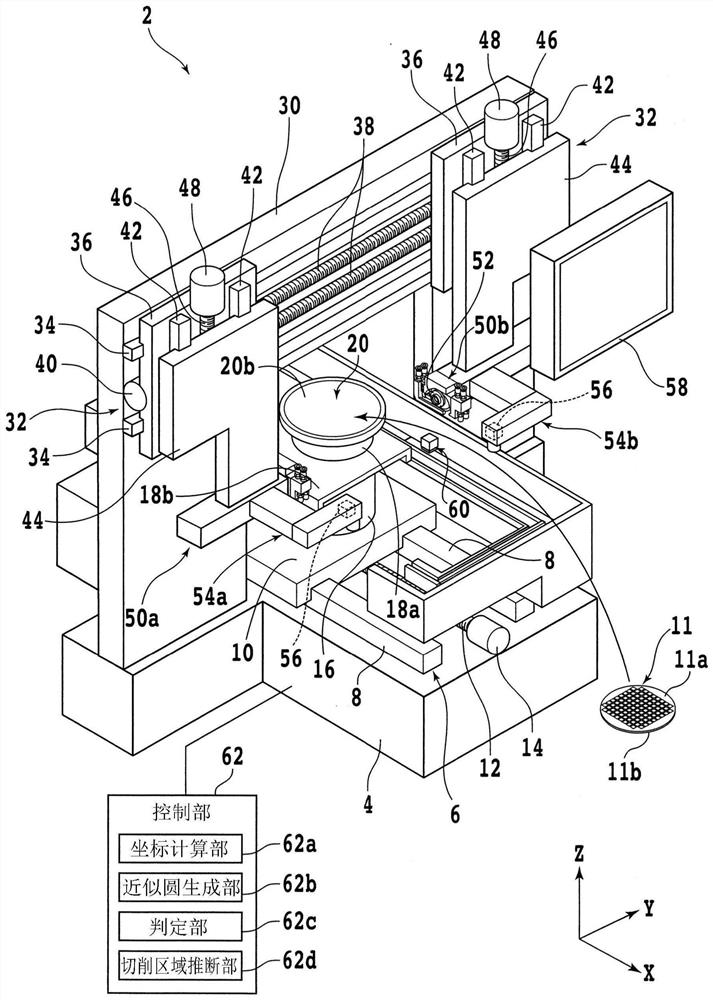
[0023] An embodiment of one embodiment of the present invention will be described with reference to the drawings. figure 1 It is a perspective view of the cutting device 2 . figure 1 The shown X-axis direction (machining feed direction, front-rear direction), Y-axis direction (index feed direction), and Z-axis direction (vertical direction, height direction) are perpendicular to each other.

[0024] In addition, in figure 1 In , a function block is used to represent a part of a constituent element. The cutting device 2 has a base 4 on which each component is mounted. An X-axis moving mechanism 6 is provided on the upper surface of the base 4 . The X-axis moving mechanism 6 has a pair of X-axis guide rails 8 substantially parallel to the X-axis direction.

[0025] An X-axis movable table 10 is slidably attached to the X-axis guide rail 8 . A nut (not shown) is attached to the lower surface (rear surface) side of the X-axis movable table 10, and the X-axis ball screw 12 sub...


PUM


Abstract

The invention provides an edge alignment method which can estimate the position of the edge of a processed object with high precision. The edge alignment method comprises the following steps: 1, a coordinate calculation step of calculating the coordinate of one point which is likely to correspond to the edge of the processed object at each of a plurality of different parts on the outer periphery of the processed object in the circumferential direction of the processed object; 2, an approximate circle generation step: generating an approximate circle by using a least square method for all the calculated coordinates; 3, an erroneously detected position exclusion step of calculating the offset between the generated approximate circle and each of all the coordinates, determining the coordinate having the largest offset as an erroneously detected position when there is a coordinate having the offset equal to or greater than a preset threshold value, and excluding the coordinate determined as the erroneously detected position from the object to be considered; and 4, a processing area estimation step of estimating the position of the edge of the processed object according to the more than three coordinates which are not excluded, and estimating the processing area according to the estimated position of the edge.

Description

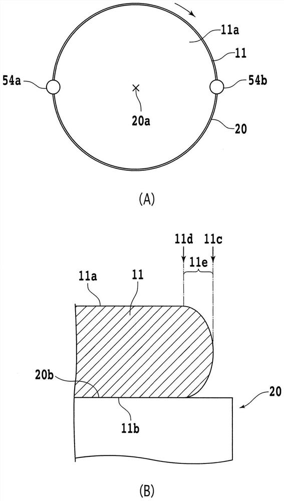
technical field [0001] The present invention relates to an edge alignment method for estimating a processing area to be processed on the outer peripheral portion of a disk-shaped workpiece. Background technique [0002] A disc-shaped workpiece such as a semiconductor wafer may have chamfered portions formed by chamfering the corners of the outer peripheral portion on the front side and the outer peripheral portion on the rear side. When the back side of the workpiece on which the chamfered portion is formed is ground to a thickness of, for example, half or less, a sharp region (so-called sharp edge) is formed on the outer peripheral portion on the back side. [0003] Cracks, nicks, etc. are easily formed at sharp edges. In addition, there is a concern that cracks may spread starting from cracks or the like formed on sharp edges, thereby damaging the workpiece. Therefore, in order to prevent the formation of sharp edges, there is known an edge trimming technique in which a ...

Claims


Application Information

Patent Timeline
Patent Type & Authority Applications(China)
IPC IPC(8): H01L21/67H01L21/68
CPCH01L21/67265H01L21/681B28D5/024B28D5/029B28D5/0064B28D5/0082G06T7/64G06T2207/30164B24B9/065B24B49/12B24B41/068G05B19/402G05D3/20G06T7/73
Inventor 小松淳牧野香一
Owner DISCO CORP
Learn More