
Internal-combustion engine

An internal combustion engine and fuel technology, applied in mechanical equipment, engine components, engine control, etc., can solve problems such as reducing the adhesion of deposits, and achieve the effect of reducing costs

Active Publication Date: 2018-05-25
TOYOTA JIDOSHA KK
View PDF8 Cites 0 Cited by
  • Summary
  • Abstract
  • Description
  • Claims
  • Application Information

AI Technical Summary

Problems solved by technology

If cracks are formed, the adhesion of the sediment will be reduced

Method used


Image

  • Internal-combustion engine
  • Internal-combustion engine
  • Internal-combustion engine

Examples


no. 2 Embodiment approach

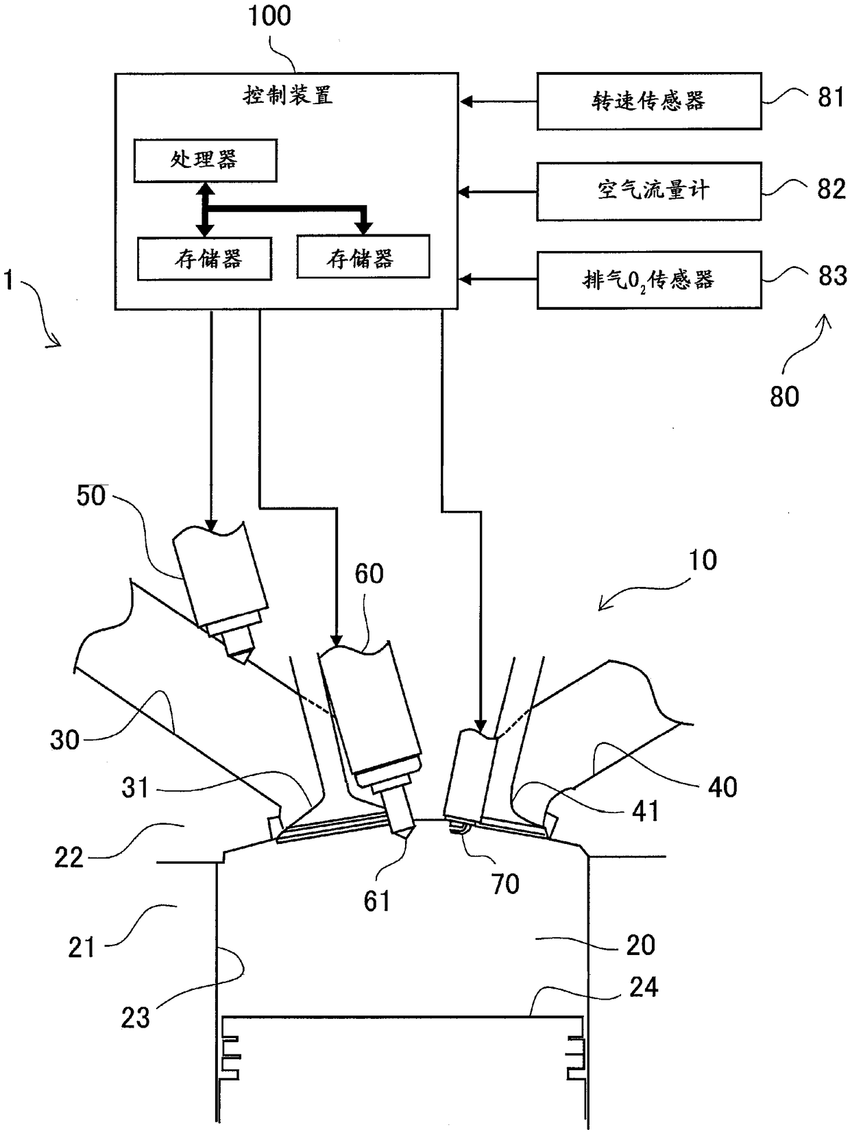
[0148] In the second embodiment of the present invention, the sediment estimation process (step S120 ) is different from that of the first embodiment. Other than that, it is the same as that of the first embodiment. Duplicate descriptions are appropriately omitted.

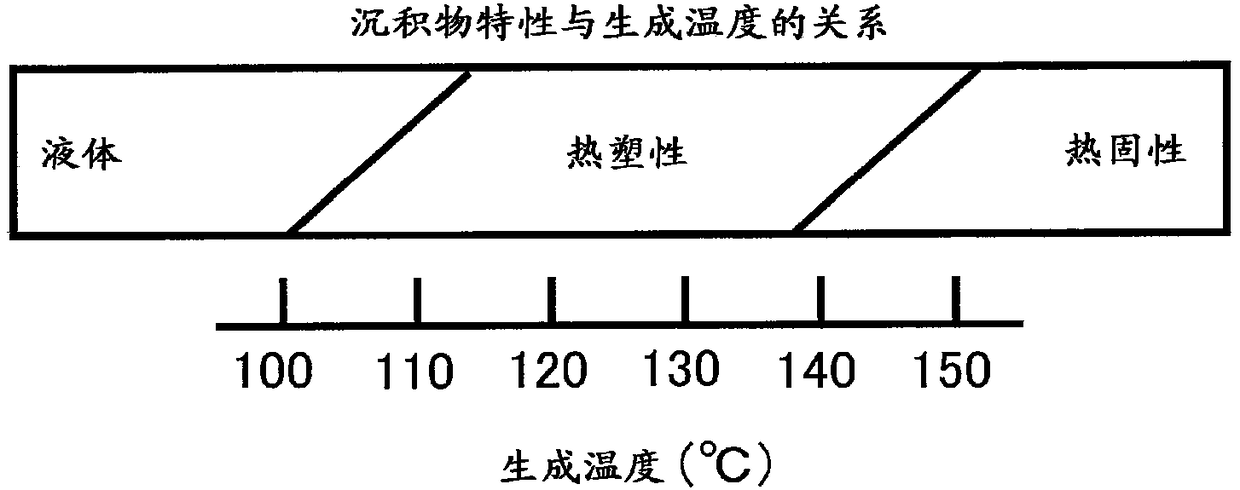
[0149] In the sediment estimation process of the second embodiment, the control device 100 (estimation unit 120) monitors Figure 6 Feedback corrections as shown are substituted for the count Z. When the feedback correction amount exceeds the allowable value Dth (in Figure 6 In the example shown, it is time ta), and the control device 100 estimates that thermoplastic deposits have been formed in the nozzle holes 61 .

[0150] Furthermore, not only thermoplastic deposits but also thermoset deposits lead to an increase in the amount of feedback correction. This means that it can be said that the estimation accuracy of the second embodiment is lower than that of the first embodiment. However, even if the estima...


PUM


Abstract

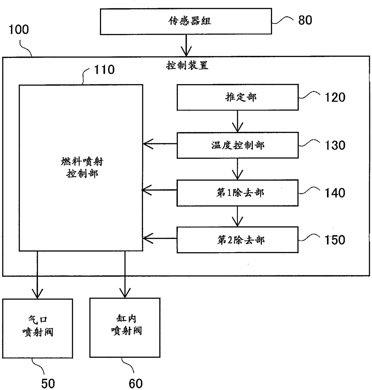
An internal-combustion engine can remove thermoplastic deposits piled in an injection hole portion of a direct fuel injector, and includes: the direct fuel injector directly injecting fuel into a combustion chamber; and a control device. The control device performs: presumption processing that presumes, based on an operating condition of the internal-combustion engine, that a thermoplastic depositis formed on an injection hole portion of the direct fuel injector; temperature control processing that increases a temperature of the injection hole portion when the thermoplastic deposit is presumed to be formed; and first removal processing that injects the fuel from the direct fuel injector after the temperature control processing.

Description

technical field [0001] The present invention relates to a technique for removing deposits formed in injection hole portions of direct fuel injectors of internal combustion engines. Background technique [0002] There is known an internal combustion engine provided with an in-cylinder injection valve for directly injecting fuel into a combustion chamber. The injection hole at the tip of the in-cylinder injection valve is exposed to the combustion gas in the combustion chamber. Therefore, deposits originating from the fuel remaining in the injection hole are accumulated in the injection hole. Deposits can cause reduced flow of fuel through the injection holes and / or changes in the spray pattern, which deteriorate emission characteristics. Therefore, it is important to remove deposits formed in the injection hole portion. As techniques related to the removal of deposits, the following techniques are known. [0003] Patent Document 1 (JP-A-2012-62858) discloses an in-cylinde...

Claims


Application Information

Patent Timeline
Patent Type & Authority Applications(China)
IPC IPC(8): F02M61/18F02M53/04F02D41/30F02D41/24F02D41/34
CPCF02D41/2454F02D41/3094F02D41/34F02M53/04F02M61/18F02M2200/00F02M53/06F02M69/046F02D41/3836F02D2200/0602F02D2041/389F02M65/008F02D41/14F02D41/402
Inventor 北爪芳之高田典史羽原辉晃
Owner TOYOTA JIDOSHA KK
Learn More