Plug connection for directly electrically contacting a circuit board

一种印刷电路板、连接部的技术,应用在接合/断开连接部件的装置、连接装置的零部件、电路等方向,能够解决影响压紧弹簧几何尺寸和插接力等问题,达到提高小型化程度、优化弹簧行程的效果

Inactive Publication Date: 2014-01-01
ROBERT BOSCH GMBH
View PDF3 Cites 2 Cited by
  • Summary
  • Abstract
  • Description
  • Claims
  • Application Information

AI Technical Summary

Problems solved by technology

This adversely affects the geometry and insertion force of the compression spring;

Method used


Image

  • Plug connection for directly electrically contacting a circuit board
  • Plug connection for directly electrically contacting a circuit board
  • Plug connection for directly electrically contacting a circuit board

Examples


Embodiment Construction

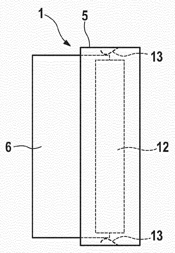
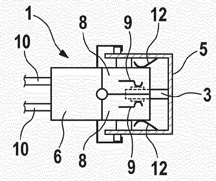
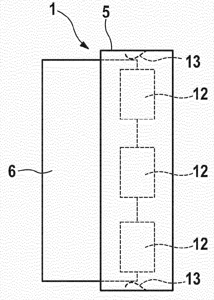
[0023] exist Figure 1a , 1b The plug connection 1 shown in is used for electrical direct contact on a printed circuit board 3 , also referred to as a "control device", with a contact surface ("bottom") 2, wherein the contact surface 2 can be arranged on the printed circuit board 3 Or it is arranged on both sides of the printed circuit board 3 .

[0024] A plug-in receptacle 5 that is open in the plug-in direction 4 and is provided with plug-in flanges or plug-in slots is provided on the printed circuit board 3 , in the region of its contact surface 2 , which is aligned with the plug-in direction. 4 protrudes oppositely into the plug receptacle. A plug (for example a cable harness plug) 6 is inserted into the plug receptacle 5 in the plug-in direction 4 and has two contact carrier halves 8 , which are hingedly connected to one another in 7 . as in Figure 1b As shown in , the printed circuit board 3 is inserted between the two contact carrier halves 8 , which in this case m...


PUM


Abstract

The invention relates to a plug connection (1) for directly electrically connecting contact surfaces (2) on a circuit board (3) having a plug receptacle (5), which is associated with the circuit board (3) and into which the circuit board (3) protrudes, having a plug (6) that can be plugged into the plug receptacle (5) and that comprises a contact carrier (8) having contact elements (9) for directly electrically contacting the contact surfaces (2) of the circuit board (3), and having a pressure spring device (11) for pressing the contact elements (9) of the contact carrier (8) against the contact surfaces (2) of the circuit board (3), wherein according to the invention the pressure spring device (11) is provided in the plug receptacle (5).

Description

technical field [0001] The invention relates to a plug connection of the type according to claim 1 for direct electrical contacting of contact areas on a printed circuit board. Background technique [0002] Control devices generally comprise a printed circuit board on which the electronic components are positioned, and a housing. In engine control systems, blades are usually mounted on printed circuit boards in order to form an electrical connection between the cable harness plug and the printed circuit board. The knife strip is therefore represented as an additional component when assembling the control device. The so-called direct electrical contact means that the blades are omitted in the direct electrical contact and the individual poles of the cable harness are in direct contact with the printed circuit board. For this purpose, electrical contact surfaces (“lands”) are provided on the printed circuit board, which contact surfaces are contacted via contact elements and...

Claims


Application Information

Patent Timeline
Patent Type & Authority Applications(China)
IPC IPC(8): H01R12/87
CPCH01R12/721H01R13/62H01R12/00H01R12/87H01R13/193H01R13/6658
Inventor F.泽尔默H.布施勒J.施泰因M.舍恩费尔德P.雷拜因U.施马茨M.克勒克尔M.弗莱格
Owner ROBERT BOSCH GMBH
Why Eureka
Try Eureka