
Low shearing adjusting valve

A regulating valve, low shear technology, applied in the wellbore/well valve device, wellbore/well components, earthwork drilling and other directions, can solve the problems of affecting the use effect, large shear force of the injected solution, etc.

Active Publication Date: 2014-01-08
ZHEJIANG JINLONG AUTOMATIC CONTROL EQUIP
View PDF5 Cites 6 Cited by
  • Summary
  • Abstract
  • Description
  • Claims
  • Application Information

AI Technical Summary

Problems solved by technology

[0003] The technical problem to be solved by the present invention is to solve the problem that the traditional valve will generate a large shear force on the injection solution when adjusting the flow rate, which seriously affects its use effect

Method used


Image

  • Low shearing adjusting valve

Examples


Embodiment Construction

[0011] The present invention will be described in detail below in conjunction with the accompanying drawings.

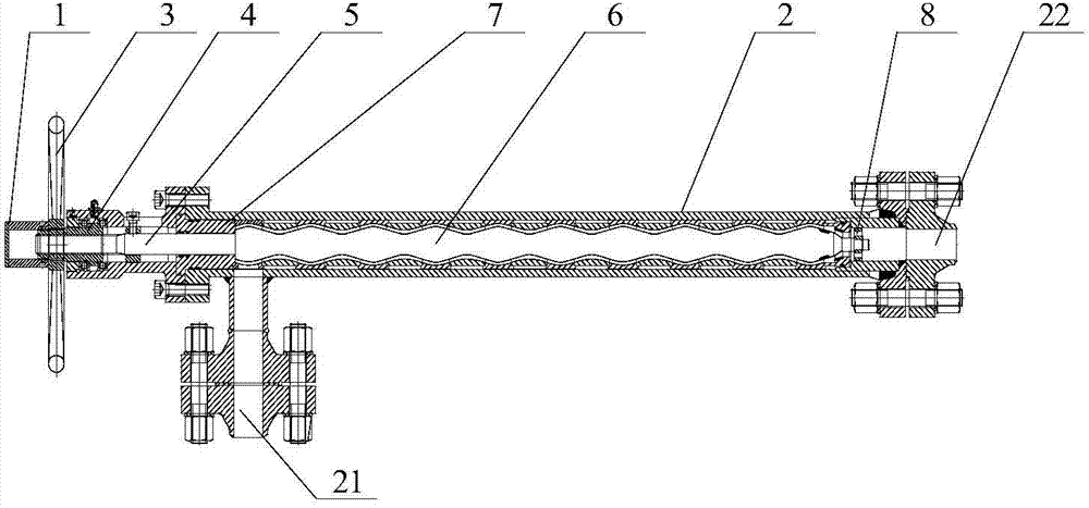
[0012] Such as figure 1 As shown, the low-shear regulating valve provided by the present invention includes a valve body and a regulating device. The valve body is in the shape of a straight tube, and includes a mediation part 1 and a valve cylinder 2 arranged in sequence. The regulating part 1 is provided with a screw nut 4, The lead screw nut 4 is clamped in the matching slot on the inner wall of the adjustment part 1, and can rotate around its central axis in the slot. The front side wall and the rear end of the valve cylinder 2 are respectively provided with water inlets 21 And the water outlet 22, between the adjustment part 1 and the valve cylinder 2 is provided with a sealing letter 7, the middle of the sealing letter 7 is a circular passage, an O-ring is installed in the passage, and the passage is also provided with an O-ring. The sealing letter 7 can well ...


PUM


Abstract

The invention discloses a low shearing adjusting valve which comprises a valve body and an adjusting device. The valve body comprises an adjusting part and a valve cylinder which are arranged front and back in sequence. A lead screw nut is arranged in the adjusting part. The lead screw nut is clamped in a clamping groove in the inner wall of the adjusting part, and the lead screw nut is matched with the clamping groove. The lead screw nut can rotate around the center axis of the lead screw nut in the clamping groove. The adjusting device comprises an adjusting handle and an adjusting rod. The adjusting handle and the lead screw nut are fixed. The adjusting rod comprises a mounting part and a rod body which are arranged front and back in sequence. The mounting part and the lead screw nut are mounted in a threaded mode. The rod body is arranged in the valve cylinder and comprises a plurality of back-cutting cones which are connected front and back in sequence in a head-to-head-tail-to-tail mode. According to the low shearing adjusting valve, the adjusting handle and the adjusting rod are arranged, the adjusting rod can be driven to move front and back by rotating the adjusting handle lead screw nut, and accordingly the function that flow is adjusted by changing the cross section area of a flow channel is achieved, the area of the flow channel is changed gradually during an adjusting process, generated shearing force is small, and the using effect of solution injection cannot be affected.

Description

technical field [0001] The present invention relates to regulating valves, in particular to low shear regulating valves. Background technique [0002] At present, polymer flooding is one of the main measures to enhance oil recovery during the development of oilfields in the ultra-high water-cut period. Inject fluid sweep volume to enhance oil recovery. Due to the different geological conditions of each oilfield, the polymer injection volume of each well is also different, which requires the adjustment of the flow through the valve. Since the injected polymer is a pseudoplastic fluid in non-Newtonian fluid, if it is sheared during the flow process The force will make the viscosity of the injected liquid lower, and when the flow is adjusted with a conventional valve, a large shear force will be generated on the injected solution, and its viscosity will be reduced by nearly 40%, which seriously affects its use effect. At present, the polymer injection process in domestic oilf...

Claims


Application Information

Patent Timeline
Patent Type & Authority Applications(China)
IPC IPC(8): E21B34/02
Inventor 余金海池爱文陈锭镍许明伟
Owner ZHEJIANG JINLONG AUTOMATIC CONTROL EQUIP
Learn More