Arrangement structure of pneumatic water supply pump set and water supply booster pump arrangement method thereof

A steam-driven feedwater pump and layout structure technology, applied to pumps, piston pumps, machines/engines, etc., can solve problems such as inconvenient maintenance of large platforms, poor drainage of exhaust pipes, and influence on safe operation of feedwater pump steam turbine 1, etc., to achieve Save the initial investment, save the power consumption of the factory, and ensure the effect of water drainage

Active Publication Date: 2014-01-08
CHINA POWER ENG CONSULTING GRP CORP EAST CHINA ELECTRIC POWER DESIGN INST
View PDF5 Cites 0 Cited by
  • Summary
  • Abstract
  • Description
  • Claims
  • Application Information

AI Technical Summary

Problems solved by technology

[0006] Although this arrangement not only solves the problem of power consumption of the feedwater prepump 4, but also allows the deaerator 5 to be arranged at a low position, but since the feedwater prepump 4, the main feedwater pump 2 and the feedwater pump steam turbine 1 are all arranged in the The zero-meter floor 6 cannot conveniently use the large platform of the operation floor 8 for maintenance
In addition, there is a problem of poor water drainage in the exhaust pipe of the feedwater pump turbine 1, which affects the safe operation of the feedwater pump turbine 1

Method used


Image

  • Arrangement structure of pneumatic water supply pump set and water supply booster pump arrangement method thereof
  • Arrangement structure of pneumatic water supply pump set and water supply booster pump arrangement method thereof
  • Arrangement structure of pneumatic water supply pump set and water supply booster pump arrangement method thereof

Examples


Embodiment Construction

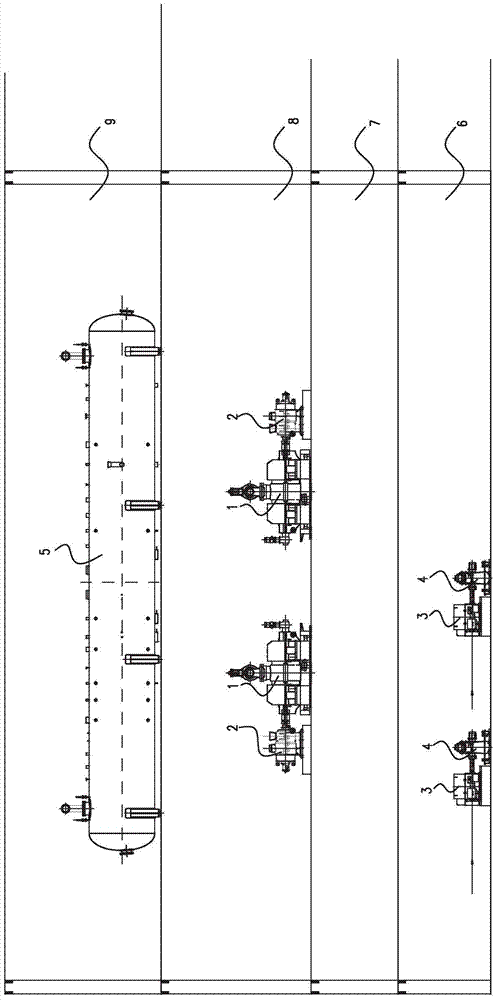
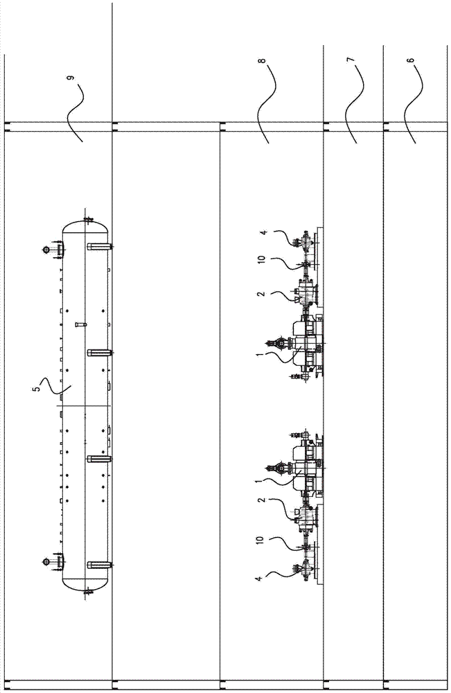
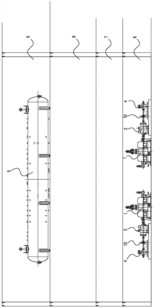
[0029] Preferred embodiments of the present invention will be described in detail below with reference to the accompanying drawings, so as to understand the purpose, features and advantages of the present invention more clearly. It should be understood that the embodiments shown in the drawings are not intended to limit the scope of the present invention, but only to illustrate the essence of the technical solutions of the present invention.

[0030] The steam-driven feed-water pump set in the embodiments mentioned below is aimed at the steam-driven feed-water pump set of 2×50% capacity. Those skilled in the art should understand after reading this disclosure that the steam-driven feedwater pump set proposed by the present invention is also applicable to a 1×100% capacity steam-driven feedwater pump set.

[0031] Figure 4 It shows a schematic diagram of the arrangement structure of the steam-driven feed water pump set according to the first embodiment of the present inventio...


PUM


Abstract

The invention discloses an arrangement structure of a pneumatic water supply pump set and method. The pneumatic water supply pump set is arranged in a steam engine room of a power plant, the pneumatic water supply pump set comprises a water supply pump turbine, a primary water supply pump, a water supply booster pump and a speed regulation device, and a zero meter layer, an interlayer and an operating layer are arranged in the steam engine room. The pneumatic water supply pump set further comprises a power generator, and the power generator and the water supply pump turbine are arranged coaxially. The primary water supply pump and the water supply pump turbine are arranged in the operating layer, and the water supply booster pump is arranged in the zero meter layer. The power generator is connected with the water supply pump turbine through the speed regulation device, and the power generator provides power for the booster pump to drive the water supply booster pump. According to the arrangement structure of the pneumatic water supply pump set, the power generated by the power generator drives the water supply booster pump which is arranged at a low position, and the auxiliary power is saved. A deaerator is arranged at a relative low position, and the primary civil engineering investment is saved. In addition, the operating layer can be very conveniently used for carrying out maintenance on equipment, and smooth drainage of a steam discharge pipe of the water supply pump turbine is guaranteed at the same time.

Description

technical field [0001] The invention relates to thermal power generation equipment, in particular to the arrangement structure of steam-driven feed water pumps in the thermal power generation equipment. Background technique [0002] At present, the water supply system of large and medium-sized thermal power plants in China generally adopts steam-driven water supply pumps. The steam-driven feedwater pump unit is mainly composed of feedwater pump steam turbine, main feedwater pump, feedwater front pump and gear box (or hydraulic coupling). The relative positional relationship and driving relationship of each component not only affects the power consumption of the factory, but also affects the arrangement height of the deaerator. [0003] Figure 1-3 It is a schematic diagram of the layout structure of the steam-driven feed water pump group in the prior art. like figure 1 As shown, the feedwater prepump 4 is arranged on the zero-meter floor 6, driven by the feedwater prepum...

Claims


Application Information

Patent Timeline
Patent Type & Authority Applications(China)
IPC IPC(8): F04B35/04
Inventor 申松林袁军蒋健施刚夜林磊
Owner CHINA POWER ENG CONSULTING GRP CORP EAST CHINA ELECTRIC POWER DESIGN INST
Why Eureka
Try Eureka