Steam high-temperature condensate water waste heat recovery system and method

A waste heat recovery system, high-temperature condensation technology, applied in heat recovery systems, residential hot water supply systems, heating methods, etc., can solve problems such as electric pump cavitation, cooling water consumption, energy waste, etc., to achieve unbalanced and economical energy effect

Pending Publication Date: 2021-08-06
CHINA UNITED NORTHWEST INST FOR ENG DESIGN & RES
View PDF0 Cites 1 Cited by
  • Summary
  • Abstract
  • Description
  • Claims
  • Application Information

AI Technical Summary

Problems solved by technology

[0002] At present, the industrial application is generally to directly pump the high-temperature condensed water of steam to the soft water tank of the boiler room or introduce it into the cooling pool to inject cooling water for cooling and then discharge it directly. The boiler room cannot use higher temperature condensed water, so it can only be discharged locally, resulting in a serious waste of energy
[0003] When the steam high temperature condensate is directly pumped to the soft water tank of the boiler room, the following common problems will be caused: as the high temperature condensate continuously enters the soft water tank, the temperature of the water tank will be very high
High temperature condensate can easily cause electric pump cavitation
When the steam high-temperature condensed water is introduced into the cooling pool for cooling and then discharged directly, not only the condensed water and the heat carried by itself are wasted, but also a large amount of cooling water is consumed, resulting in a huge waste of heat and water
[0004] None of the existing technologies starts from the steam system as a whole and treats steam condensate as conventional hot water. However, the four links of the steam system (steam generation, steam delivery, steam use, and condensate recovery) affect each other and restrict each other. The presence of flash steam and the steam-water two-phase flow of condensate makes the recycling of condensate different from that of conventional hot water

Method used


Image

  • Steam high-temperature condensate water waste heat recovery system and method

Examples


Embodiment Construction

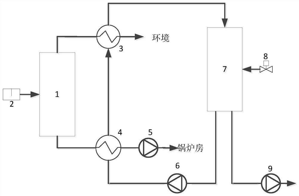
[0033] The following will clearly and completely describe the technical solutions in the embodiments of the present invention with reference to the accompanying drawings in the embodiments of the present invention. Obviously, the described embodiments are some of the embodiments of the present invention, but not all of them. Based on the embodiments of the present invention, all other embodiments obtained by persons of ordinary skill in the art without making creative efforts belong to the protection scope of the present invention.

[0034] In describing the present invention, it should be understood that the terms "center", "longitudinal", "transverse", "upper", "lower", "front", "rear", "left", "right", " The orientation or positional relationship indicated by "vertical", "horizontal", "top", "bottom", "inner", "outer", "side", "end", "side" etc. is based on the Orientation or positional relationship is only for the convenience of describing the present invention and simplif...


PUM


Abstract

The invention discloses a steam high-temperature condensate water waste heat recovery system and method. A drain valve is arranged at the inlet end of a flash tank, the outlet end of the flash tank is divided into two paths, one path is connected with a low-resistance steam-water heat exchanger, the other path is connected with a boiler room after passing through a water-water heat exchanger and a condensate water delivery pump, the water-water heat exchanger is connected with the inlet end of a heat storage tank through the low-resistance steam-water heat exchanger, the outlet end of the heat storage tank is divided into two paths, one path is connected with the water-water heat exchanger through a circulating water delivery pump, the other path is connected with a domestic hot water delivery pump, and an automatic water replenishing valve is arranged on the heat storage tank. According to the steam high-temperature condensate water waste heat recovery system and method, the problems of delivery electric pump cavitation, flue gas energy saver damage, unsmooth drainage of upstream equipment, heat pollution of flash steam and the like existing in the past are solved, meanwhile, energy is saved, imbalance of a heat using time period can be achieved through the heat storage tank, and peak elimination and valley filling are carried out.

Description

technical field [0001] The invention belongs to the technical field of new energy and energy saving, and in particular relates to a waste heat recovery system and method of steam high-temperature condensed water. Background technique [0002] At present, the industrial application is generally to directly pump the high-temperature condensed water of steam to the soft water tank of the boiler room or introduce it into the cooling pool to inject cooling water for cooling and then discharge it directly. The boiler room cannot use higher temperature condensed water, so it can only be discharged locally, resulting in a serious waste of energy. [0003] When pumping high temperature steam condensate directly to the soft water tank of the boiler room, it will bring the following common problems: as the high temperature condensate continuously enters the soft water tank, the temperature of the water tank will be very high. This will not only cause the soft water tank to emit steam ...

Claims


Application Information

Patent Timeline
Patent Type & Authority Applications(China)
IPC IPC(8): F22B3/04F22B37/26F22B37/46F28D21/00F24D17/00
CPCF22B3/04F22B37/26F22B37/46F24D17/0005F28D21/0012F28D21/0014Y02B30/18Y02B30/56
Inventor 岳慧峰廖茂志张蕊刘挺张海涛张银全袁欣
Owner CHINA UNITED NORTHWEST INST FOR ENG DESIGN & RES
Why Eureka
Try Eureka