Measuring device and method for target line-of-sight angel offset and distance
What is AI technical title?
AI technical title is built by Patsnap AI team. It summarizes the technical point description of the patent document.
A measurement device and line-of-sight technology, which is used in measurement devices, radio wave measurement systems, and electromagnetic wave re-radiation, etc., can solve the problem of difficulty in extracting the target line-of-sight angle offset of narrow-pulse laser beams, and large-scale ranging by pulse time-of-flight method. Low accuracy, inability to dynamically measure distance and angle, etc., to achieve the effect of reducing digital acquisition and processing, high sensitivity, and reducing difficulty and complexity
Active Publication Date: 2015-06-24
INST OF OPTICS & ELECTRONICS - CHINESE ACAD OF SCI
View PDF6 Cites 0 Cited by
Summary
Abstract
Description
Claims
Application Information
AI Technical Summary
This helps you quickly interpret patents by identifying the three key elements:
Problems solved by technology
Method used
Benefits of technology
Problems solved by technology
[0005] The purpose of the present invention is to solve the problems of difficulty in extracting the target line-of-sight angle offset of a narrow pulse laser beam, low extraction accuracy, and low accuracy of large-scale ranging by the pulse time-of-flight method. At the same time, the existing laser tracking equipment cannot complete dynamic distance measurement. and angle problems, providing a device and method for target line of sight angle offset and relative distance
Method used
Image
Click on the blue label to locate the original text in one second.
Reading with bidirectional positioning of images and text.
Examples
Embodiment Construction
[0059] In order to make the object, technical solution and advantages of the present invention clearer, the present invention will be described in further detail below in conjunction with specific embodiments and with reference to the accompanying drawings.
[0060] The circuit diagram of the analog circuit, video amplifier circuit, summation circuit, automatic gain amplifier circuit, AD conversion circuit, time discrimination circuit, CPU+FPGA digital circuit can be designed directly in the application circuit in the datasheet of the device, and the analog circuit It is the core of the whole circuit, so the attached drawing only shows the circuit diagram of the analog circuit part.
[0061] Below in conjunction with accompanying drawing, provide a kind of target line of sight angle offset and the method for distance measurement, its steps and conditions are as follows:
[0062] exist figure 1 and image 3 It shows that the target line-of-sight angle offset and the distance ...
PUM
Abstract
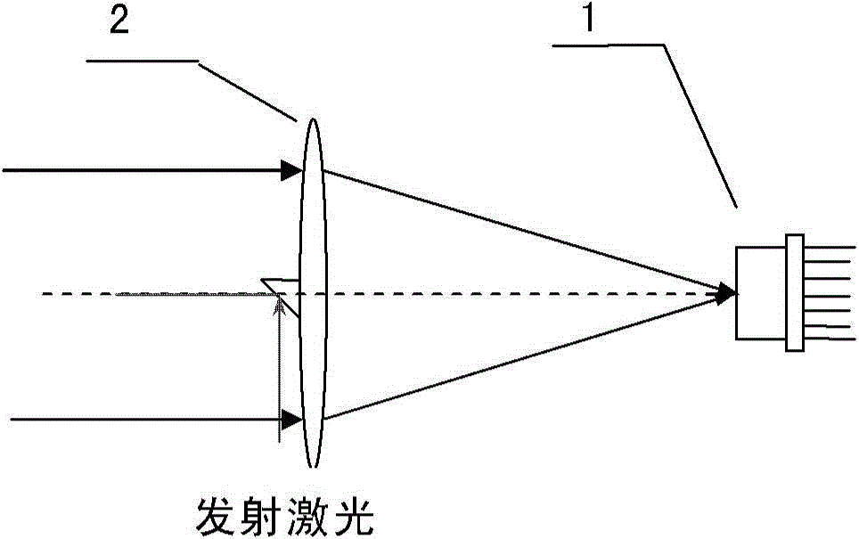
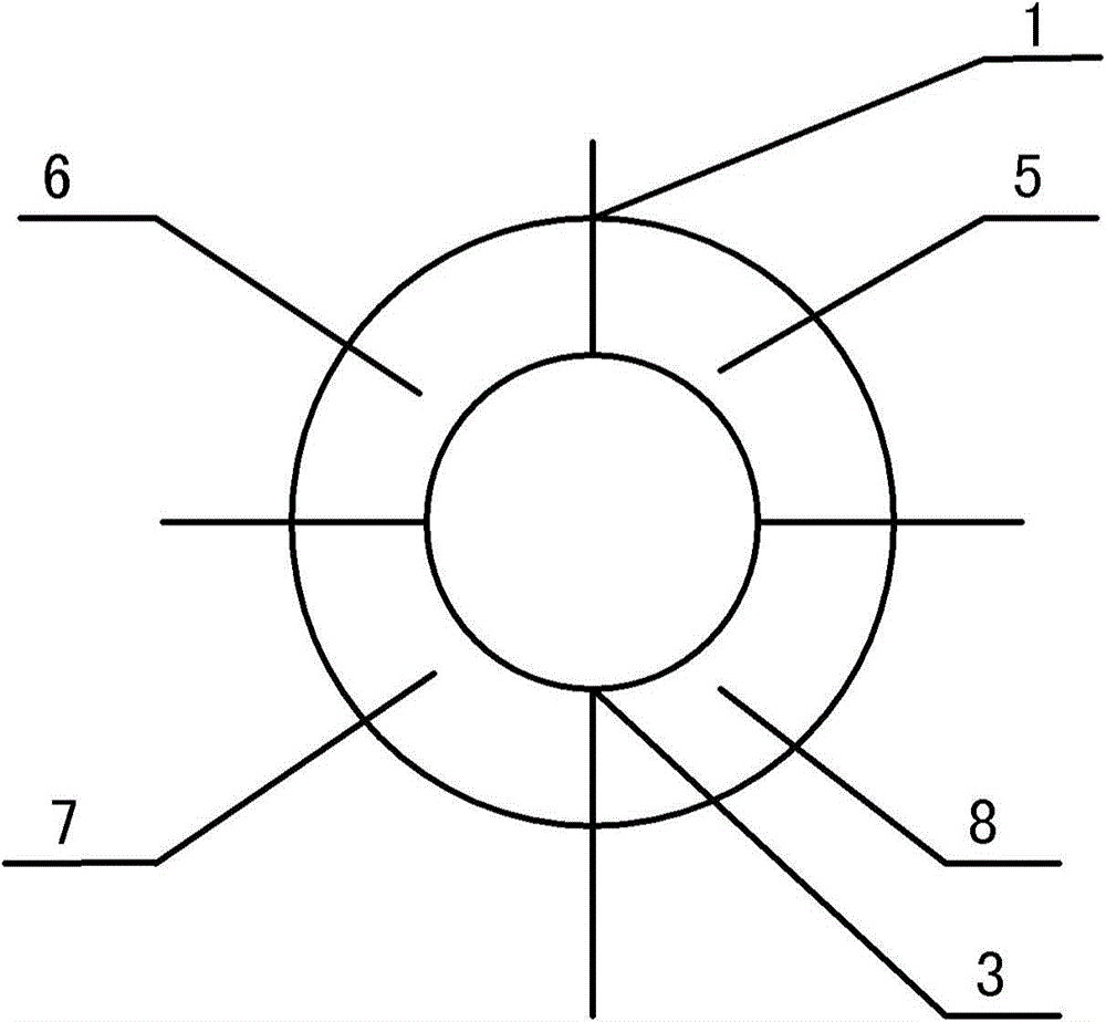
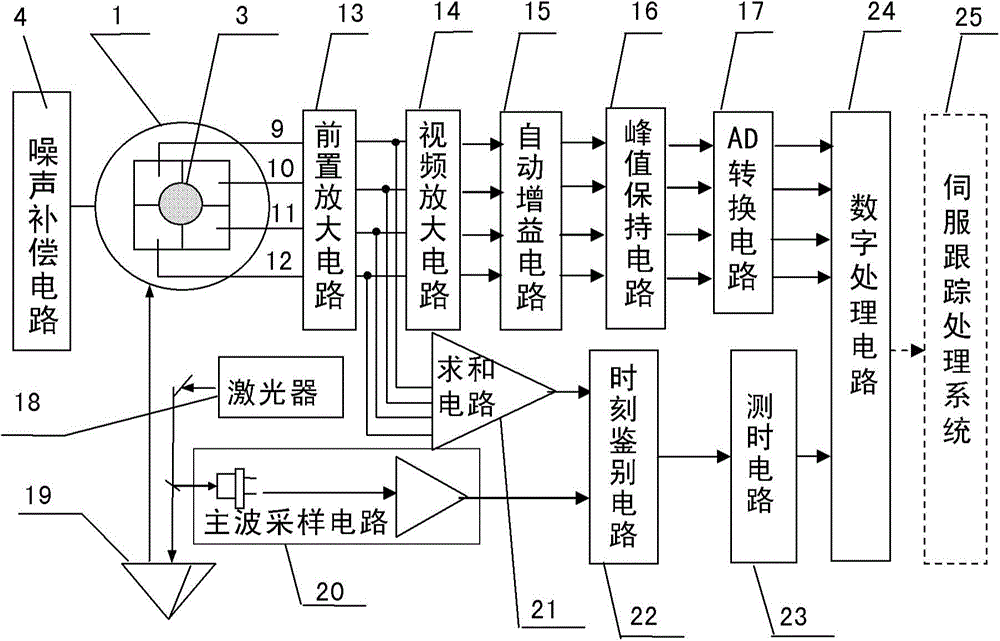
The invention provides a measuring device and method for the target line-of-sight angel offset and distance. The device is composed of a four-quadrant avalanche photodetector, a receiving and sending optical unit, a noise compensation circuit, a four-circuit front amplification circuit, a video amplification circuit, an automatic gain amplification circuit, a peak keeping circuit, an AD conversion circuit, a laser, a dominant wave sampling circuit, a summing circuit, a time identifying circuit, a time test circuit and a digital processing circuit, wherein the receiving and sending optical unit enables narrow pulse laser rays emitted by the laser to be converged on the photoelectric detector to form echo light spots after target reflection, photovoltaic conversion of the four-quadrant avalanche photodetector, front amplification, video amplification and automatic gain amplification are conducted, narrow-pulse peak keeping is conducted, transmission of the AD conversion circuit is conducted, and the digital processing circuit extracts the digital line-of-sight angel offset; summing is conducted on the four-circuit front amplification circuit, the dominant wave sampling circuit is combined, the time identifying circuit determines laser emitting and echo coming and returning time, the time is transmitted to the time identifying circuit to be measured, and the digital processing circuit decodes the corresponding distance.
Description
technical field [0001] The invention belongs to the technical field of photoelectric tracking and measurement, and relates to a device and method for measuring the offset of target line-of-sight angle and distance, especially capable of realizing the extraction of target line-of-sight angle offset and distance measurement in space rendezvous and docking. Background technique [0002] At present, the main photodetectors used to measure the offset of the target line-of-sight angle include charge-coupled device (CCD), active pixel sensor (APS), position sensor (PSD), and quadrant detector (QD). The data output by the charge-coupled device can directly reflect the position of the light spot on the photosensitive surface, and then obtain the offset of the target line-of-sight angle according to its offset relative to the center of the photosensitive surface. However, the charge-coupled device has many pixels, and the data that needs to be processed In addition, the sensitivity of...
Claims
Application Information
Patent Timeline
Application Date:The date an application was filed.
Publication Date:The date a patent or application was officially published.
First Publication Date:The earliest publication date of a patent with the same application number.
Issue Date:Publication date of the patent grant document.
PCT Entry Date:The Entry date of PCT National Phase.
Estimated Expiry Date:The statutory expiry date of a patent right according to the Patent Law, and it is the longest term of protection that the patent right can achieve without the termination of the patent right due to other reasons(Term extension factor has been taken into account ).
Invalid Date:Actual expiry date is based on effective date or publication date of legal transaction data of invalid patent.
Patent Type & AuthorityPatents(China)
IPC IPC(8): G01S17/50G01S17/66
CPCG01S7/4861G01S7/4865G01S17/42G01S17/66
Inventor冯志辉岳永坚杨武袁林晨代冬军
OwnerINST OF OPTICS & ELECTRONICS - CHINESE ACAD OF SCI

