Method and device for testing dynamic range of camera by utilizing closed LED (light emitting diode) light source lamp box

A technology of LED light source and dynamic range, which is applied in image communication, television, electrical components, etc., can solve the problems that the consistency of test results cannot be well guaranteed, the consistency of light source optical parameters is poor, and the test accuracy is affected. The test results are objective, consistent and repeatable, and the effect of improving test accuracy

Inactive Publication Date: 2014-01-08
SHANGHAI RES CENT OF ENG & TECH FOR SOLID STATE LIGHTING
View PDF4 Cites 11 Cited by
  • Summary
  • Abstract
  • Description
  • Claims
  • Application Information

AI Technical Summary

Problems solved by technology

[0009] 1. The entire test environment must be carried out in a dark room;
[0010] 2. Because there is no isolation between the back projection light source used for the transmission test card and the illumination light source used for the reflection test card, mutual crosstalk will affect the test accuracy; if the brightness output of the rear projection light source and the illumination light source are greatly increased, this The mutual crosstalk between the two light sources will be more serious;
[0011] 3. The setting of each light source parameter and the setting of the light source position adopts manual mode, and the test accuracy and consistency of the test results cannot be well guaranteed;
[0012] 4. The existing light sources usually use high-power incandescent lamps or other lamps, which have high power consumption, poor reliability, and poor consistency of optical parameters such as chromaticity and brightness of the light source.

Method used


Image

  • Method and device for testing dynamic range of camera by utilizing closed LED (light emitting diode) light source lamp box
  • Method and device for testing dynamic range of camera by utilizing closed LED (light emitting diode) light source lamp box
  • Method and device for testing dynamic range of camera by utilizing closed LED (light emitting diode) light source lamp box

Examples


Embodiment Construction

[0049] The present invention will be further described below in conjunction with the accompanying drawings and embodiments.

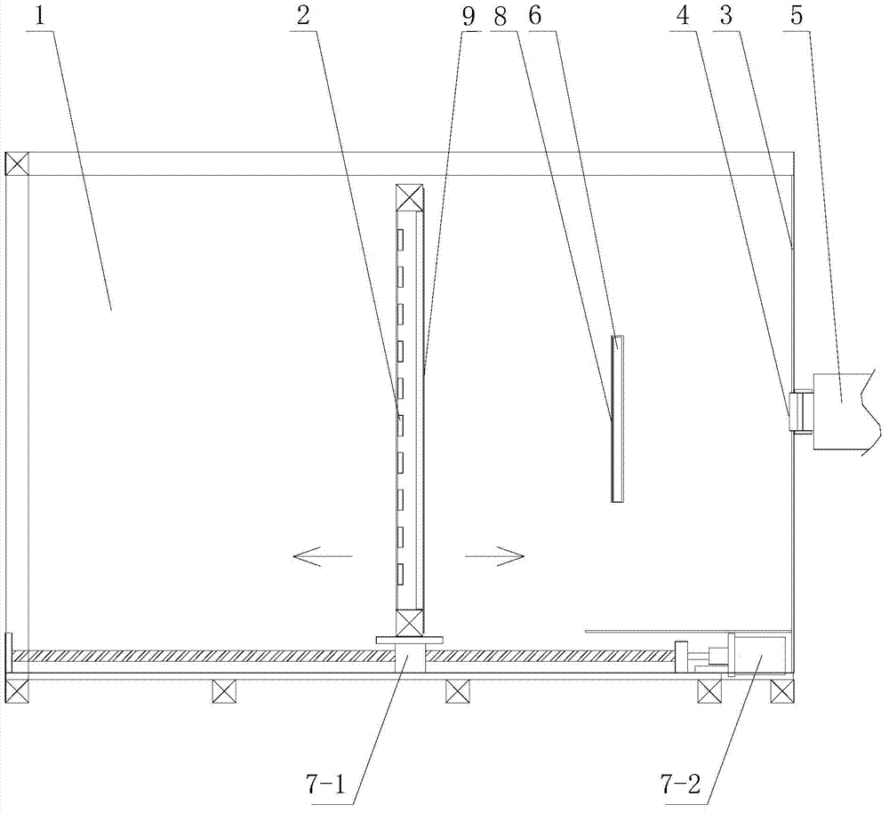
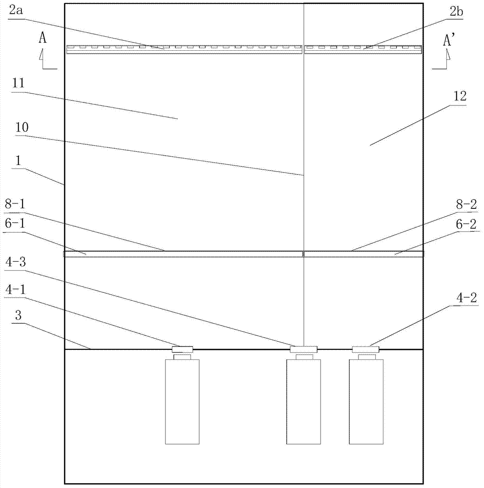
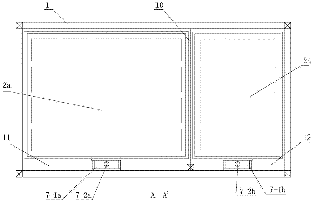
[0050] The technical solution of the present invention provides a method for testing the dynamic range of a camera with a closed LED light source light box, which specifically includes: setting a closed box structure; The airtight box is divided into two adjacent and independent first test space and second test space; by setting two adjacent airtight test spaces, two independent airtight light box systems are formed, providing Isolated closed test light source environment;

[0051] At the front of the first / second test space, a front panel with a camera test hole is arranged;

[0052] In the first / second test space, the first / second LED light sources are set respectively; by setting two groups of controlled LED light sources whose light domains are independent of each other, mutual crosstalk between the two groups of test light sources can be avoided, ...


PUM


Abstract

The invention relates to a method and a device for testing a dynamic range of a camera by utilizing a closed LED (light emitting diode) light source lamp box, and belongs to the field of testing. The method comprises the following steps of partitioning a closed box into two adjacent mutually independent first/second testing spaces; arranging a front plate with a camera testing hole in the front part of each testing space; respectively arranging an LED light source in the two testing spaces; respectively arranging a transparent testing card between each LED light source and each front plate; arranging movable sliding rails with movable sliding blocks in the longitudinal directions of the two testing spaces; arranging the LED light sources on the movable sliding blocks; connecting control ends of the LED light sources, control ends of the movable sliding rails and an image output end of camera lens to be tested with I/O ports of a control computer. According to the method and the device for testing the dynamic range of the camera by utilizing the closed LED light source lamp box, which are disclosed by the invention, an closed testing light source environment isolated from the outside is provided, the two light sources are completely independent without any crosstalk, and the configuration of optical parameters of the LED light sources and the adjustment of the distances and the positions of the LED light sources and a device to be tested are controlled by the computer, so that the whole testing device is convenient to operate, and the measurement accuracy is largely improved.

Description

technical field [0001] The invention belongs to the field of optical testing, in particular to a testing method and device for measuring the dynamic range of a camera imager. Background technique [0002] When high-brightness areas illuminated by strong light sources (sunlight, lamps, or reflections, etc.) and relatively low-brightness areas such as shadows and backlights exist in the image at the same time, the image output by the camera will appear bright areas that become white due to overexposure. However, dark areas become black due to underexposure, seriously affecting image quality. [0003] The performance of the camera in the brightest area and the darker area in the same scene is limited. This limitation is commonly referred to as "dynamic range". [0004] It can be seen that the "dynamic range" of the camera refers to the camera's ability to adapt to the light reflection of the scene in the shooting scene, specifically refers to the range of brightness (contrast)...

Claims


Application Information

Patent Timeline
Patent Type & Authority Applications(China)
IPC IPC(8): H04N17/00
Inventor 张群力李抒智杨卫桥
Owner SHANGHAI RES CENT OF ENG & TECH FOR SOLID STATE LIGHTING
Why Eureka
Try Eureka