Riveting machine

A technology of riveting machine and riveting components, which is applied in the field of mechanical equipment, can solve the problems of large moving distance of the riveting head, crushing of the workpiece to be riveted by the riveting head, time-consuming and labor-intensive problems, and achieves the effect of high safety and improved riveting quality

Inactive Publication Date: 2014-01-15
SIP GOLDWAY TECH
View PDF5 Cites 0 Cited by
  • Summary
  • Abstract
  • Description
  • Claims
  • Application Information

AI Technical Summary

Problems solved by technology

[0002] During the riveting process of the existing riveting machine, in order to avoid the riveting head moving too far, causing the riveting head to crush the workpiece to be riveted, the moving distance of the riveting head is usually preset in the control system to control the punching distance of the riveting head for the rivet. However, to control the moving distance of the riv

Method used


Image

  • Riveting machine

Examples


Embodiment Construction

[0018] The present invention will be described in detail below with reference to the various embodiments shown in the accompanying drawings. However, these embodiments do not limit the present invention, and structural, method, or functional transformations made by those of ordinary skill in the art based on these embodiments are all included in the protection scope of the present invention.

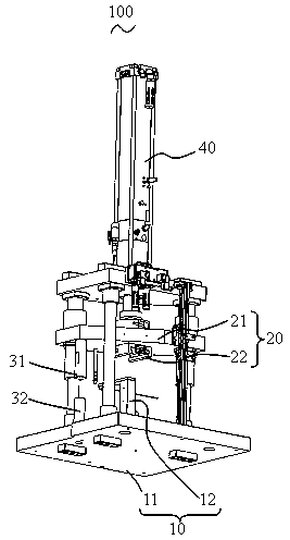
[0019] ginseng figure 1 As shown, the present invention provides a riveting machine 100 with high safety. During the riveting process, the riveting head 22 will not squeeze the workpiece to be riveted, thereby ensuring the safety of the workpiece to be riveted.

[0020] Wherein, the riveting machine 100 provided by the present invention includes:

[0021] A positioning assembly 10 for fixing a workpiece to be riveted, a riveting assembly 20 located above the positioning assembly 10, and a power assembly 30 connecting the riveting assembly 20, the power assembly 30 controls the riveting ...


PUM


Abstract

The invention provides a riveting machine which comprises a positioning assembly, a riveting assembly and a power assembly. The positioning assembly is used for fixing a workpiece to be riveted. The riveting assembly is located above the positioning assembly, and the power assembly is connected with the riveting assembly. The power assembly controls the riveting assembly to move toward or move away from the positioning assembly, and the riveting assembly and the positioning assembly are provided with a first abutting-against part and a second abutting-against part respectively. The first abutting-against part and the second abutting-against part extend oppositely so that the minimum distance between the riveting assembly and the positioning assembly can be achieved. In comparison with the prior art, according to the riveting machine, due to the fact that the first abutting-against part and the second abutting-against part extending oppositely are arranged between the riveting assembly and the positioning assembly, the minimum distance between the first abutting-against part and the second abutting-against part is achieved in the process that the riveting assembly moves toward the positioning assembly, a riveting heat in the riveting assembly is prevented from pressing and damaging the workpiece to be riveted and therefore riveting quality of the riveting machine is improved.

Description

technical field [0001] The invention relates to the field of mechanical equipment, in particular to a riveting machine. Background technique [0002] In the riveting process of the existing riveting machine, in order to prevent the riveting head from moving too far, causing the riveting head to crush the workpiece to be riveted, the distance of the riveting head moving is usually preset in the control system to control the punching distance of the riveting head to the rivet. However, the control system is used to control the moving distance of the riveting head. For different rivets and workpieces to be riveted, it is necessary to reset the moving distance of the riveting head in the control system, which is time-consuming and laborious, and seriously affects the adaptability of the riveting machine. The riveting efficiency of the riveting machine is reduced, and it is not suitable for the fierce market competition. [0003] Therefore, it is necessary to propose a new rivet...

Claims


Application Information

Patent Timeline
IPC IPC(8): B21J15/10B21J15/30
Inventor 李佳
Owner SIP GOLDWAY TECH
Why Eureka
Try Eureka