Synchronizer ring

A technology of synchronous ring and synchronizer, which is applied in the field of synchronous ring, can solve problems such as flange damage, and achieve the effect of easy ductility

Inactive Publication Date: 2014-01-15
SULZER FRICTION SYST GERMANY
View PDF9 Cites 12 Cited by
  • Summary
  • Abstract
  • Description
  • Claims
  • Application Information

AI Technical Summary

Problems solved by technology

[0008] Flanges designed too narrow or additionally exceeding a certain minimum length tend to fail due to bending

Method used


Image

  • Synchronizer ring
  • Synchronizer ring
  • Synchronizer ring

Examples


Embodiment Construction

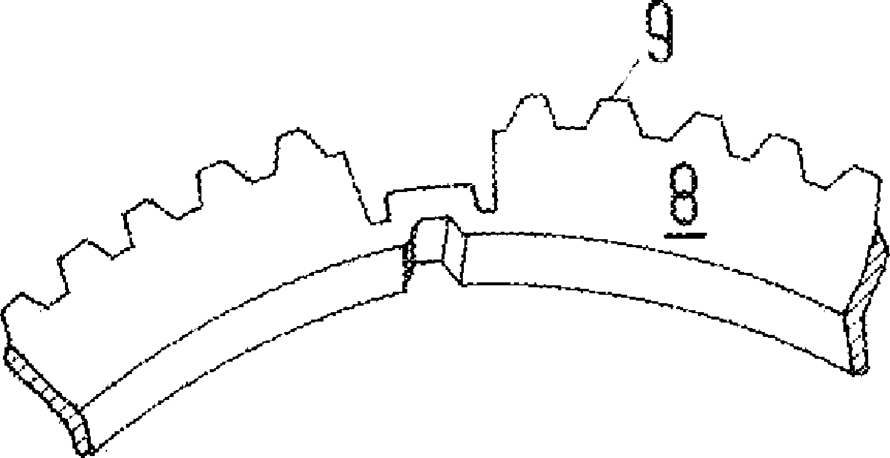
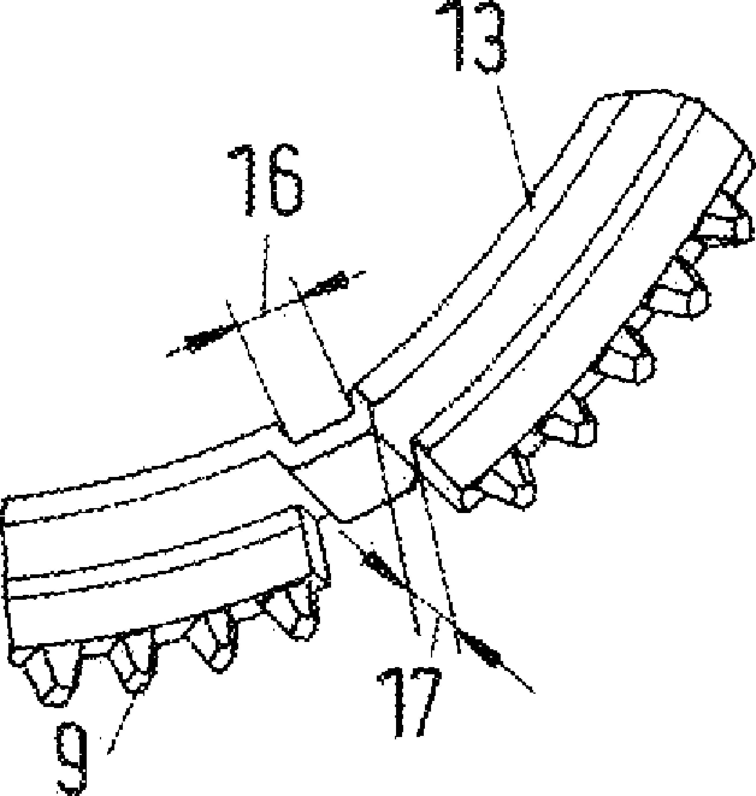
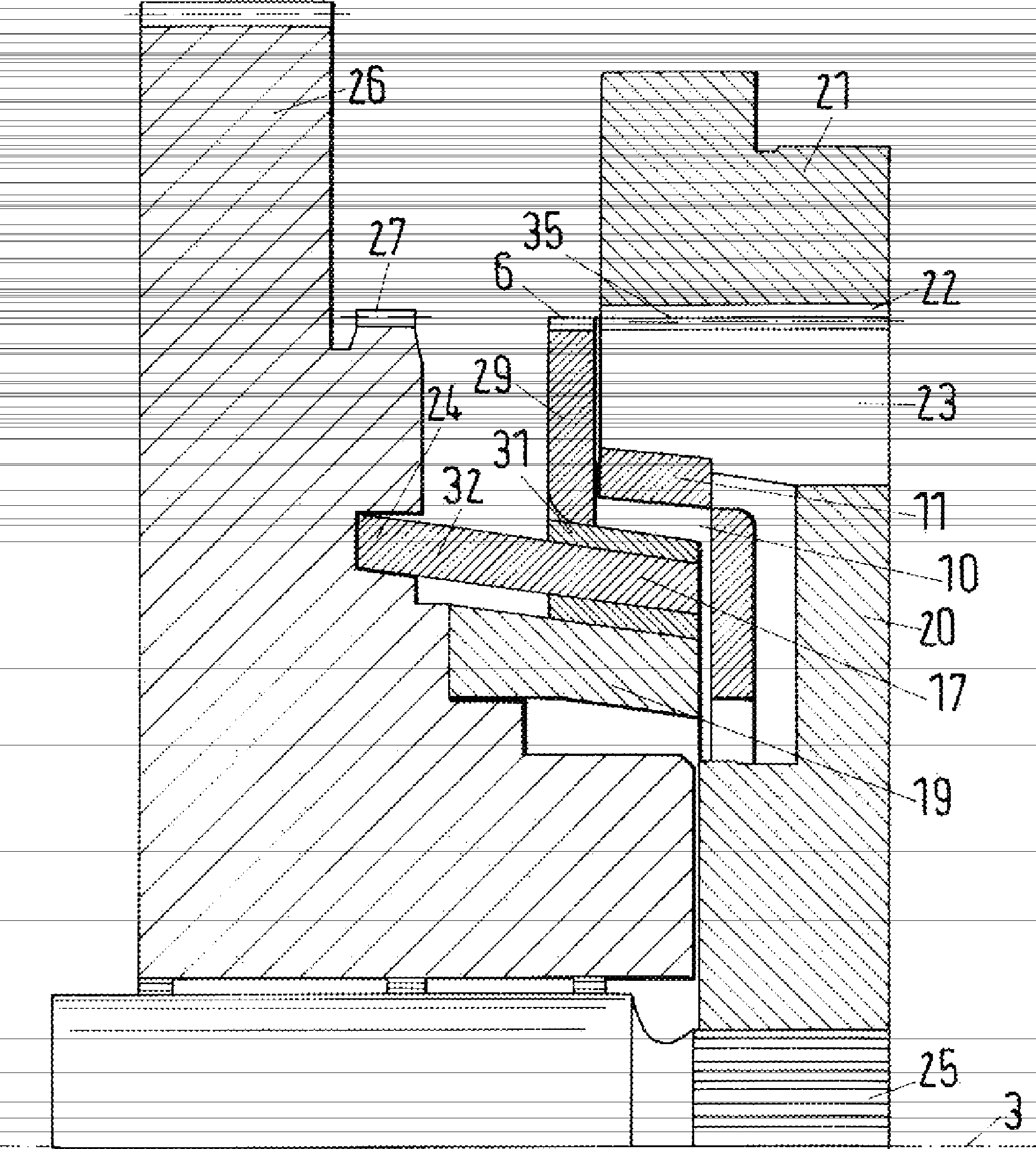
[0042] Basis for synchronizers for shiftable gearshift transmissions Figure 1a The synchro ring 1 has a ring body 2 . The ring body 2 is arranged around the synchronizer ring axis 3 . The ring body has an inner friction surface 4 and an outer mounting surface 5 . The inner friction surface 4 and the outer mounting surface 5 delimit the ring body 2 in the radial circumferential direction. The ring body 2 has a toothing 6 extending from a gear base bar 7 which surrounds the ring body radially and is present at the end face of the ring body. The gear base bar 7 supports the teeth of the toothed arrangement 6 . The recess 10 is arranged at the inner friction surface 4 of the ring body 2 such that the radius 14 of the inner friction surface at the end face 13 in the region of the recess 10 is greater than the radius 12 of the inner friction surface 4 .

[0043] The recess 10 has a substantially rectangular cross section. The longitudinal sides of the rectangle run substantiall...


PUM


Abstract

A synchronizer ring for a synchronizer of a switchable gear changing transmission, includes a ring body having a synchronizer ring axis, which ring body has an inner friction surface and an outer installation surface, wherein the inner friction surface and the outer installation surface bound the ring body as jacket surfaces. The ring body has an end face and a gear surface opposite the end face, wherein the synchronizer ring has a width (15) which corresponds to the shortest distance between the end face and the gear surface and the jacket surfaces extend between the end face and the gear surface, wherein the ring body has a toothed arrangement which extends radially outwardly from the outer installation surface, wherein the toothed arrangement has a crown gear which extends from the gear surface via a part of the width of the ring body in the direction of the end face, characterized by a recess which is arranged at the inner friction surface of the ring body, so that the radius of the inner friction surface in the region of the recess is larger than the radius of the inner friction surface; at the end face, and wherein a bulge is provided at the outer installation surface which is arranged in the radial direction over the recess.

Description

technical field [0001] The invention relates to a synchronizing ring of a synchronizer of a shiftable gearshift transmission and to a vehicle gearshift. Furthermore, the invention relates to a synchronizer comprising a synchronizer ring of a switchable shift transmission. Synchronizers may be used in vehicle transmissions. The invention also relates to a method of manufacturing the synchronizer ring. Background technique [0002] Synchronizing rings in mechanical shiftable transmissions are used to match the relative speeds between the gears and the transmission shafts, which are produced when shifting gears. [0003] The transmission shaft is force-transmittingly connected to the corresponding gear wheel by means of a gear arrangement, so that the output shaft can be driven at the desired number of revolutions. A plurality of gears are arranged at the output shaft with different gear ratios. Accordingly, the rotational speed of the output shaft can be correspondingly hi...

Claims


Application Information

Patent Timeline
Patent Type & Authority Applications(China)
IPC IPC(8): F16D23/02
CPCF16D23/025F16D23/04Y10T29/49467B23P15/14
Inventor U.克里斯托弗
Owner SULZER FRICTION SYST GERMANY
Why Eureka
Try Eureka