An electronic expansion valve

A technology of electronic expansion valve and valve stem, which is applied in the direction of lifting valve, valve details, valve device, etc., can solve the problems of internal leakage and reduce product reliability, so as to reduce refrigerant noise, improve reliability and reduce the occurrence of internal leakage The effect of probability

Active Publication Date: 2016-04-06
ZHEJIANG SANHUA INTELLIGENT CONTROLS CO LTD
View PDF7 Cites 0 Cited by
  • Summary
  • Abstract
  • Description
  • Claims
  • Application Information

AI Technical Summary

Problems solved by technology

[0012] First, in the structure of the above-mentioned electronic expansion valve, there are movable valve core seats 2' one by one. When the refrigerant flows forward and needs to be sealed, the valve needle part 3' needs to be sealed with the valve core valve port 2'2. The valve core seat 2' is sealed with the main valve port 1'31, so there are two sealing parts, so it is easier to cause internal leakage and reduce the reliability of the product

Method used


Image

  • An electronic expansion valve
  • An electronic expansion valve
  • An electronic expansion valve

Examples


Embodiment Construction

[0057] The core of the present invention is to provide an electronic expansion valve. On the one hand, the structural design of the electronic expansion valve can reduce the probability of internal leakage, thereby improving the reliability of the product; on the other hand, it can reduce the generation of refrigerant noise.

[0058] In order to enable those skilled in the art to better understand the technical solutions of the present invention, the present invention will be further described in detail below in conjunction with the accompanying drawings and specific embodiments.

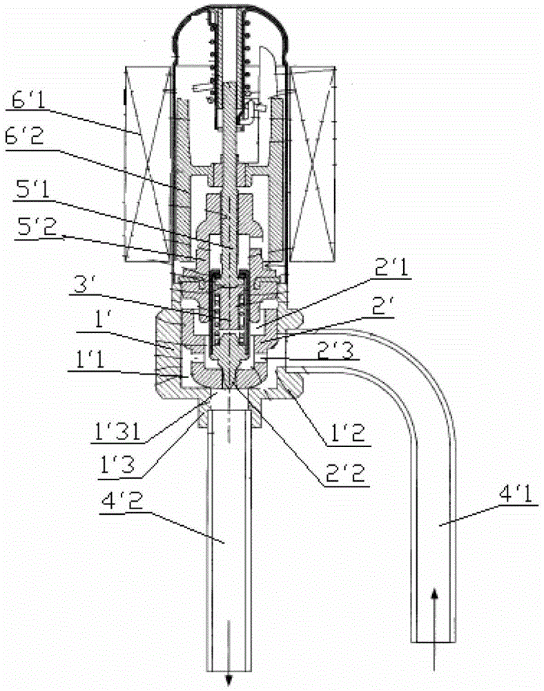
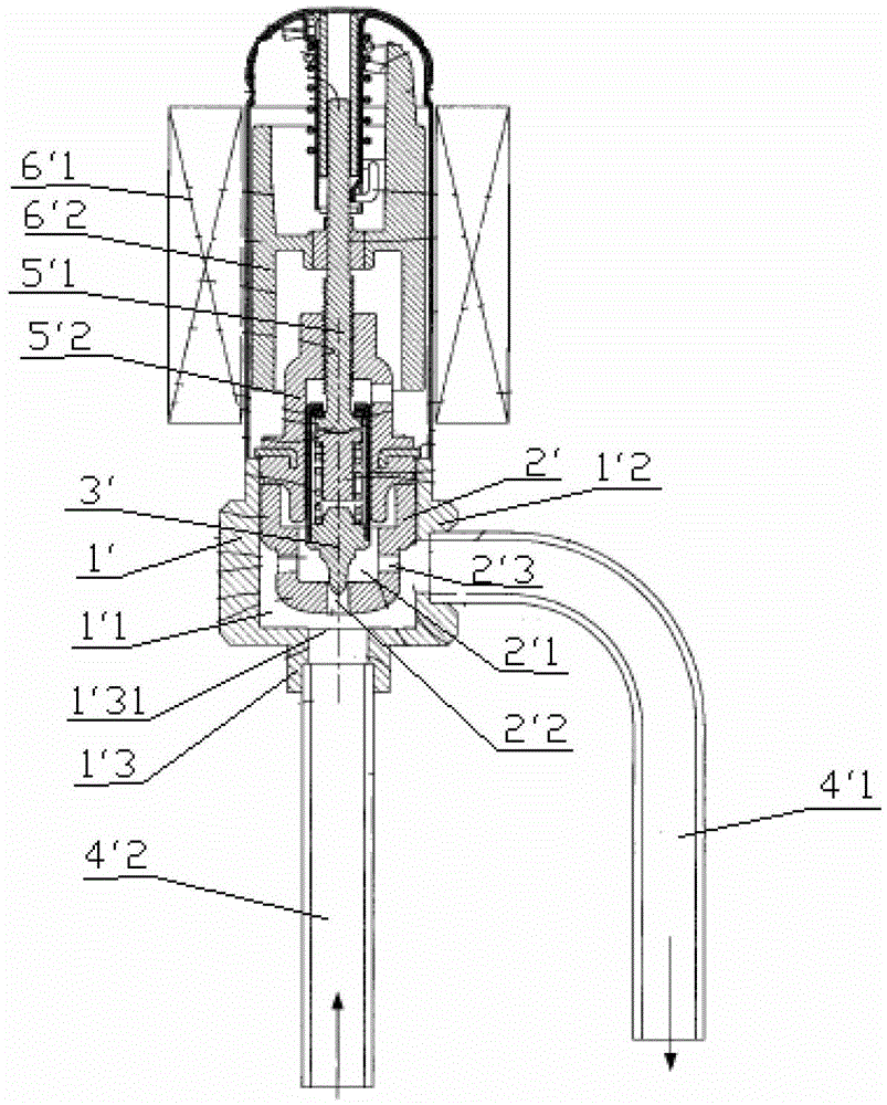
[0059] Please refer to Figure 4 , Figure 5 and Figure 6 , Figure 4 It is a structural schematic diagram of the electronic expansion valve in an embodiment of the present invention when the refrigerant flows forward; Figure 5 for Figure 4 Schematic diagram of the structure of the electronic expansion valve in the reverse flow of refrigerant; Figure 6 for Figure 4 Partial enlarged view o...


PUM


Abstract

The invention discloses an electronic expansion valve, the bottom end of the valve stem part (4) is provided with a valve stem limiting part (421), and the valve needle (3) is provided with a valve needle limiting part (31); when When the refrigerant flows in the forward direction, the valve needle (3) is subjected to the downward force of the system pressure difference, and the valve needle (3) moves downward relative to the valve stem part (4). Driven by the valve stem part (4), the valve needle ( 3) Move up and down to adjust the opening of the valve port (12) within the range less than or equal to the predetermined opening; when the refrigerant flows in the reverse direction, the pressure difference force of the valve needle (3) is upward, and the valve needle (3) is relatively As the valve stem part (4) moves upward, the valve needle (3) makes the valve port (12) conduct with an opening greater than the predetermined opening. The structural design of the electronic expansion valve can reduce the probability of internal leakage on the one hand, and reduce the generation of refrigerant noise on the other hand.

Description

technical field [0001] The invention relates to the technical field of fluid control components, in particular to an electronic expansion valve. Background technique [0002] In the air conditioner market, due to the long distance between the indoor unit and the outdoor unit, two electronic expansion valves are used, and the two electronic expansion valves must be connected in parallel with one-way valves to maximize system efficiency. Its system schematic diagram is as follows figure 1 , the working principle is briefly described as follows: [0003] During cooling: the high-temperature and high-pressure gaseous refrigerant coming out of the exhaust pipe of the compressor 7'8 passes through the D connection and E connection of the four-way valve 7'1, the outdoor exchanger 7'2 (condensation and heat release), the first one-way Valve 7'4 (the first electronic expansion valve 7'3 has no regulating effect), the second electronic expansion valve 7'5 (at this time, the second o...

Claims


Application Information

Patent Timeline
Patent Type & Authority Patents(China)
IPC IPC(8): F16K1/00F16K1/32F16K1/38F16K1/42F16K47/02F25B41/06F25B41/35
CPCF16K1/00F16K1/32F16K1/38F16K1/42F16K47/02F25B41/31Y02B30/70
Inventor 不公告发明人
Owner ZHEJIANG SANHUA INTELLIGENT CONTROLS CO LTD
Why Eureka
Try Eureka