Nuclear fusion reaction system

A reaction system and fusion reaction technology, applied in the field of continuous fusion reaction systems, can solve problems such as instability and discontinuity in fuel delivery, and achieve the effect of safe energy output

Active Publication Date: 2014-01-15
HOPE INNOVATION SHANGHAI INC
View PDF5 Cites 8 Cited by
  • Summary
  • Abstract
  • Description
  • Claims
  • Application Information

AI Technical Summary

Problems solved by technology

[0012] Current tokamak technology has turbulence-induced instabilities and laser-focus technology has fuel delivery discontinuities

Method used


Image

  • Nuclear fusion reaction system
  • Nuclear fusion reaction system
  • Nuclear fusion reaction system

Examples


Embodiment Construction

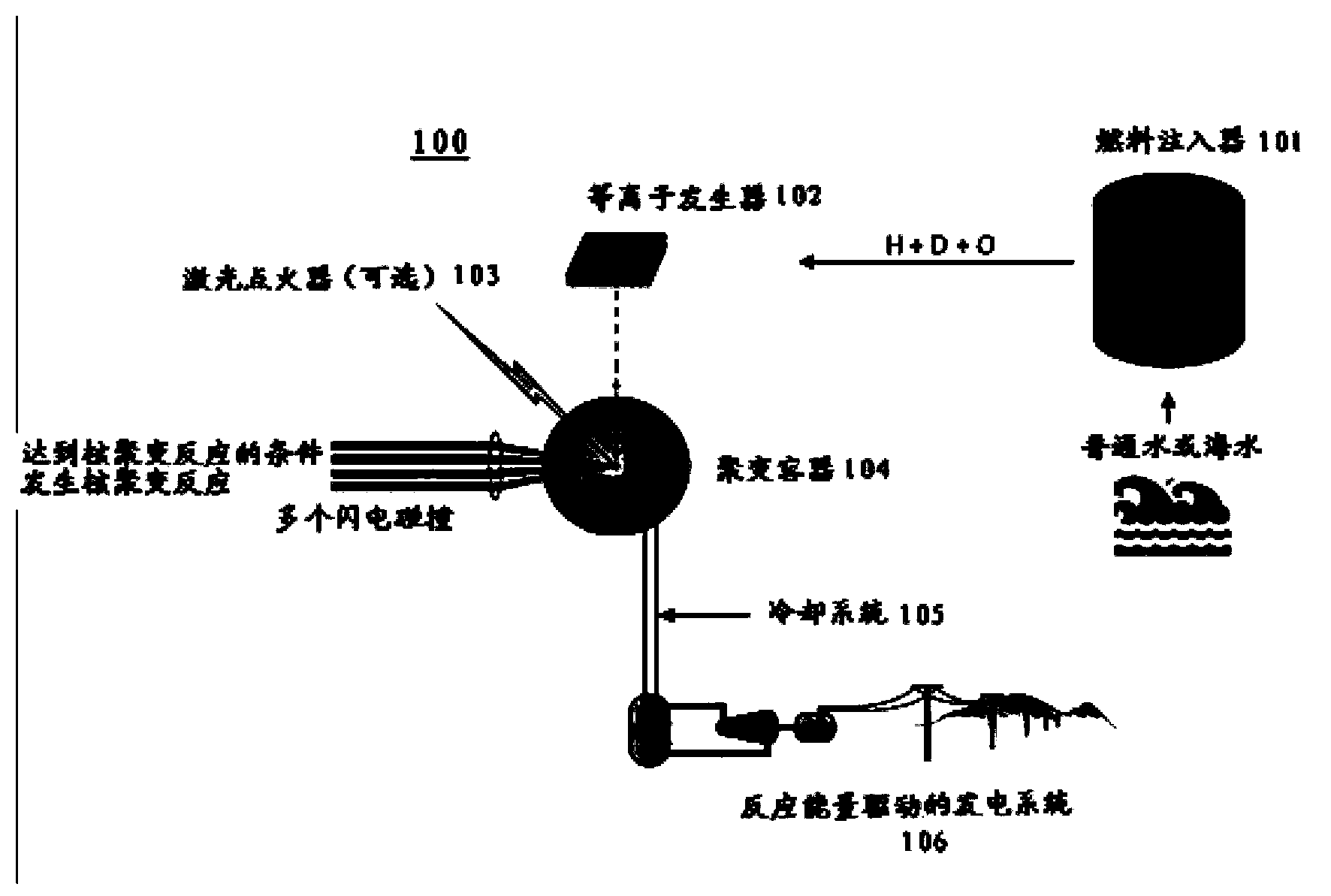
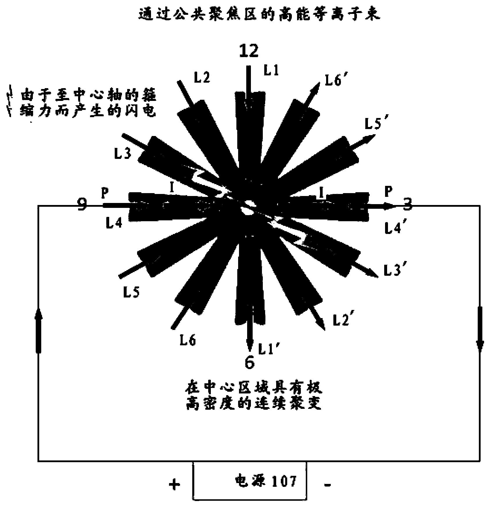
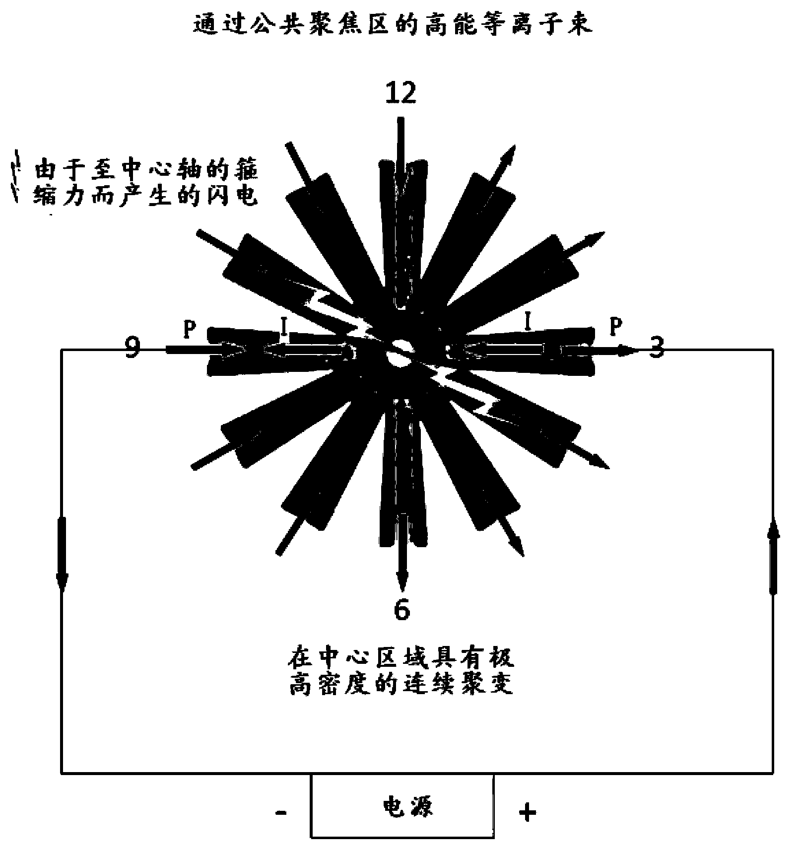
[0022] There have been many attempts at fusion by focusing beams of charged ions, but without success. The present disclosure does not simply use a beam of charged ions because the repulsive forces between like-charged ions make convergence in the central region difficult to achieve. The overall neutral, goo-like plasma is better suited for converging, and can be generated and maintained directly by current in a closed circuit. As a result, miniature lightning similar to lightning in nature can be realized. Direct multiple high-speed micro-lightnings to the same area for convergence, and trigger continuous fusion through intense thermal collisions.

[0023] Sustainable continuous nuclear fusion occurs every day at the extremely high pressures, temperatures and densities of stellar cores, providing the most valuable information for designing and testing fusion devices according to the present disclosure on Earth. The closest to Earth is the fusion that takes place in the inne...


PUM


Abstract

The present invention relates to a nuclear fusion reaction system which comprises the following components: a reaction container; a fuel injector which provides at least one thermonuclear fuel; and at least one pair of plasma generator which is adjacent to the reaction container and is used for forming plasma beams that are oriented to a gathering area in the reaction container from the thermonuclear fuel supplied from the fuel injector through applying current and pinching the plasma beams to a lightening, wherein the plasma generator causes the current to drive the lightening to impact in the gathering area for causing fusion reaction.

Description

technical field [0001] The present disclosure relates to a nuclear fusion reaction system, and more specifically, proposes a system for producing a sustained fusion reaction through the fusion fuel's lightning energy concentration. Background technique [0002] Fusion energy is produced by atomic fusion reactions, and the burning of stars we see in natural phenomena is such a reaction. In this type of fusion reaction, two lightweight nuclei fuse to form a heavier nucleus, releasing large amounts of energy. In the usual sense, this reaction can produce energy output through fusion fuel like a steam engine. More of this research focuses on how fusion reactions can be used to generate heat and drive steam turbines and generators to generate electricity. Except for the use of thermonuclear reaction materials as reaction substances in this energy conversion process, other parts are the same as ordinary coal power, oil power and gas power plants. [0003] The basic concept supp...

Claims


Application Information

Patent Timeline
Patent Type & Authority Applications(China)
IPC IPC(8): G21B1/05G21B1/11
CPCY02E30/10
Inventor 曾宪俊
Owner HOPE INNOVATION SHANGHAI INC
Why Eureka
Try Eureka