Coupling and middle chucking, conduction testing, encoding and die arraying device of detonator and automatic control method

A technology of conduction test and bayonet card, which is applied in the direction of detonators and offensive equipment, can solve the problems of difficult to ensure the accuracy of process connection, many components involved in human participation, and low degree of automation, so as to reduce the chance of personnel being injured, Low cost and the effect of improving production efficiency

Inactive Publication Date: 2014-01-22
王玉首
View PDF6 Cites 10 Cited by
  • Summary
  • Abstract
  • Description
  • Claims
  • Application Information

AI Technical Summary

Problems solved by technology

It can be seen that the above-mentioned process has a low degree of automation, slow efficiency, and many elements of human participation, which n

Method used


Image

  • Coupling and middle chucking, conduction testing, encoding and die arraying device of detonator and automatic control method
  • Coupling and middle chucking, conduction testing, encoding and die arraying device of detonator and automatic control method
  • Coupling and middle chucking, conduction testing, encoding and die arraying device of detonator and automatic control method

Examples


Example Embodiment

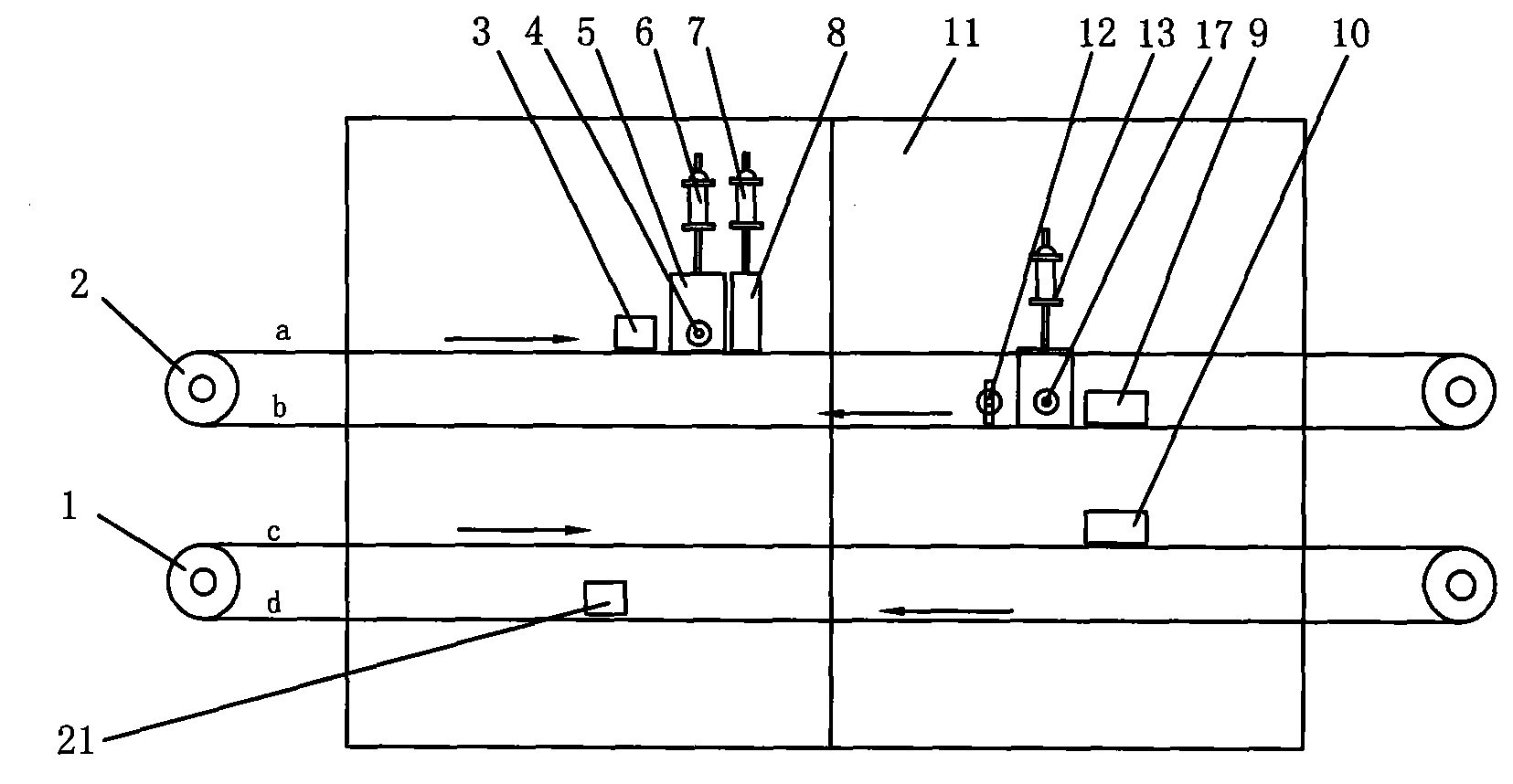
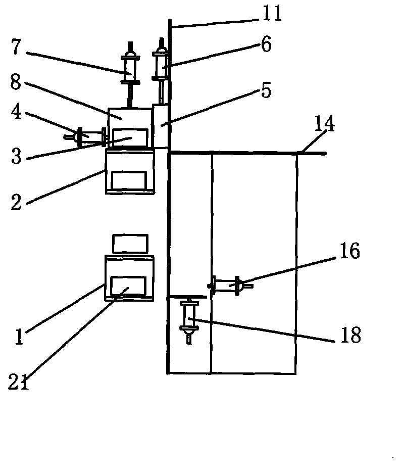
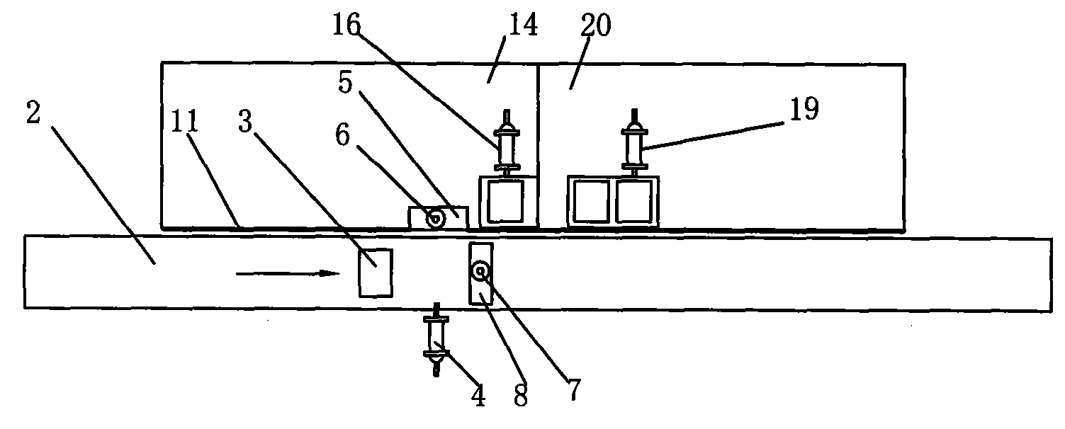
[0020] The device for testing the waist and conduction of the detonator bayonet provided by the present invention is divided by the protective plate 11 into a workpiece conveying mechanism and an operating station. The operating station refers to the bayonet bayonet station and the conduction die arrangement station, which are arranged at intervals to facilitate the transfer of workpieces between the two processes.

[0021] Such as figure 1 , image 3 As shown, the workpiece conveying mechanism includes a horizontal conveying device and a vertical conveying device. Among them, the horizontal conveying device includes an upper belt conveyor 2 and a lower belt conveyor 1, respectively responsible for the conveyance of the real mold 3 and the empty mold 21 containing the detonator to be processed, and the real code box 10 and the empty code box for encoding the processed detonator. 9's delivery.

[0022] Such as Figure 1~3 As shown, the bayonet bayonet mold divider of the present i...


PUM


Abstract

The invention provides a coupling and middle chucking, conduction testing, encoding and die arraying device of a detonator and an automatic control method and relates to the field of production of industrial explosive materials. According to the coupling and middle chucking, conduction testing, encoding and die arraying device, a protective board (11) is divided into a workpiece conveying mechanism and an operation station, wherein the workpiece conveying mechanism comprises a horizontal conveying device and a vertical conveying device; the operation station is a coupling and middle chucking station (14) and a conduction testing and die arraying station (20). The horizontal conveying device is provided with a coupling and middle chucking die splitting device and a conduction die splitting device; the coupling and middle chucking die splitting device is composed of a first port door (5), a cutting die plate (8) and a real die lateral pushing air cylinder (4); the conduction die splitting device is composed of a second port door (23), an empty encoding box die cutting air cylinder (22) and an empty encoding box lateral pushing air cylinder (12). The horizontal conveying device is used for automatically distributing and conveying a real die provided with the detonator and an empty encoding box on a belt conveyor to the operation station; the vertical conveying device is used for automatically conveying an empty die and a real encoding box back to the belt conveyor and intensive control is realized by a central processing unit; the coupling and middle chucking, conduction testing, encoding and die arraying device of the detonator has the positive effects of high efficiency, low cost and high safety guarantee coefficients.

Description

technical field [0001] The invention relates to the field of production of civil blasting equipment, in particular to an automatic conveying and production device for detonator bayonet buckle processing, conduction testing, and coded die arranging, and a method for automatically controlling it. Background technique [0002] On the current detonator production line, the stations of each process on the production line are mainly connected by manual transfer or conveyor belt. The loaded detonators are placed in the module together, transported by the conveyor belt, and arrive at the bayonet card waist processing station. The module is manually removed and placed on the station, and then the detonator is taken out for processing, and the empty module is placed on the return journey of the conveyor belt. Back on belt. After a process operation is completed, the semi-finished products formed by this process are manually collected, and then passed to the next process for processin...

Claims


Application Information

Patent Timeline
IPC IPC(8): C06C7/02
Inventor 王玉首
Owner 王玉首
Why Eureka
Try Eureka