Two-way constant force output air flotation device

A technology of constant force output and air flotation, applied in the direction of fluid pressure actuators, etc., can solve the problems of low precision of constant force output, inaccurate sensor measurement, and difficulty in maintaining a constant output force value, so as to meet assembly accuracy requirements, Processing simple effect

Active Publication Date: 2016-09-28
重庆荣宇机械制造股份有限公司
View PDF8 Cites 0 Cited by
  • Summary
  • Abstract
  • Description
  • Claims
  • Application Information

AI Technical Summary

Problems solved by technology

[0004] Aiming at the problems in the existing constant force output device that the output force value is difficult to keep constant, the sensor measurement is not accurate enough, and the constant force output accuracy is not high, the present invention provides a two-way constant force output air flotation device with accurate output force value and good stability.

Method used


Image

  • Two-way constant force output air flotation device
  • Two-way constant force output air flotation device
  • Two-way constant force output air flotation device

Examples


Embodiment Construction

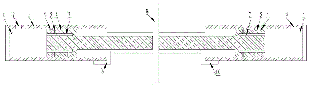
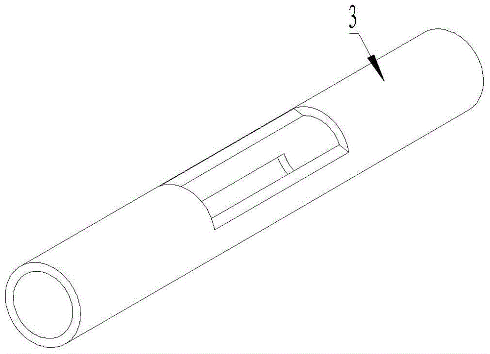
[0022] A two-way constant force output air flotation device includes a cylinder 3 , a connecting rod piston 6 , an end cover 1 , an output shaft 8 , and a limit block 10 .

[0023] The piston 6 is set in the cylinder 3, and the two ends of the cylinder 3 are sealed by the end cap 1.

[0024] The middle part of the cylinder barrel 3 is provided with two vertically symmetrical axial grooves, and limit blocks 10 are installed at both ends of the axial grooves.

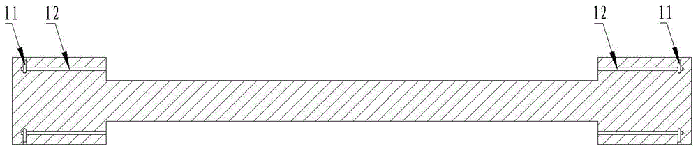
[0025] The connecting rod piston 6 includes a first piston protruding at both ends, a second piston and a piston rod in the middle. There is a very small gap between the first piston, the second piston and the cylinder 3, and the middle part of the piston rod is connected to the output shaft 8. The output shaft 8 passes through the axial groove on the cylinder 3.

[0026] Both ends of the cylinder 3 are respectively provided with a first air inlet 2 and a second air inlet 9 .

[0027] Radial throttling holes 5 are evenl...


PUM


Abstract

The invention provides a two-way constant force output air flotation device, which includes a cylinder, a connecting rod piston, an end cover, an output shaft, and a limit block. The piston is set in the cylinder, and the two ends of the cylinder are sealed by end caps. There are two symmetrical axial grooves in the middle of the cylinder, and limit blocks are installed at both ends of the axial groove. The connecting rod piston includes a first piston protruding at both ends, a second piston and a piston rod in the middle. There is a very small gap between the first piston, the second piston and the cylinder, and the middle part of the piston rod is connected The output shaft passes through the axial groove on the cylinder, and the two ends of the cylinder are respectively provided with a first air inlet and a second air inlet, and the first air inlet and the second air inlet The air port is respectively connected to the proportional valve and the air storage tank through the air pipe. Both the cylinder and the piston are designed in one piece, and radial orifices are evenly distributed on the connecting rod and piston. The structure and air supply method are simple, the bearing capacity is good, and high-precision constant force output can be realized.

Description

technical field [0001] The invention relates to a constant force output device. Background technique [0002] According to different application environments and application requirements, there are various structures and implementation methods for constant force output. Dynamic constant force output refers to loading a constant force value on a dynamically moving target workpiece. [0003] Hanging the target workpiece through weights is the simplest and most commonly used method of applying constant force. Since the mass of the weight is constant, the force acting on the target workpiece remains unchanged, but when the target workpiece is accelerating or decelerating, the weight The weight will generate an additional force on the target workpiece due to the influence of its own inertial force, and the greater the mass of the weight, the greater the effect, so this method is only suitable for low-speed or uniform-speed movement of the target workpiece. Torque motors, hydrau...

Claims


Application Information

Patent Timeline
Patent Type & Authority Patents(China)
IPC IPC(8): F15B15/14
Inventor 孙建辉刘坤
Owner 重庆荣宇机械制造股份有限公司
Why Eureka
Try Eureka