Spring bracket allowing on-spot adjustment

A spring bracket and adjustable technology, which is applied in the direction of pipeline supports, pipes/pipe joints/fittings, mechanical equipment, etc., can solve the problems of pipeline safety operation, pipeline operation safety, pipeline operation safety hazards, etc., to achieve pipeline operation Safe and reliable, avoiding frictional thrust, and conducive to safe operation

Active Publication Date: 2014-01-22
JIANGSU MINGJIANG MACHINERY MFG
View PDF9 Cites 8 Cited by
  • Summary
  • Abstract
  • Description
  • Claims
  • Application Information

AI Technical Summary

Problems solved by technology

[0003] (1) The spring preload in the existing spring bracket must be completed in the equipment manufacturer, and the preloaded spring cannot be adjusted according to the site conditions at the construction site
[0004] (2) Due to the large deviation between the calculated weight of the pipeline design and the design position of the pipeline support and the construction environment on site, there is a large deviation between the calculated preload value of the existing spring bracket design and the preload value actually required on site, and there are potential safety hazards in pipeline operation
[0005] (3) Long-term operation of high-temperature and high-pressure pipelines and pipeline vibration during pipeline operation cause the spring in the spring bracket to lose part of the elasticity of the spring over time, and there are potential safety hazards in pipeline operation
[0006] (4) The spring preload in the existing spring bracket must be completed in the equipment manufacturer. Due to various reasons such as equipment transportation and installation, the positioning pin of the spring bracket is easy to fall off, and the spring bracket cannot be preloaded and restored on site. The construction only preloads the spring symbolically according to experience, so that the spring preload design value is quite different from the actual required preload value, and the pipeline has hidden dangers in safe operation

Method used


Image

  • Spring bracket allowing on-spot adjustment
  • Spring bracket allowing on-spot adjustment

Examples


Embodiment Construction

[0020] The present invention will be further described below in conjunction with specific drawings and embodiments.

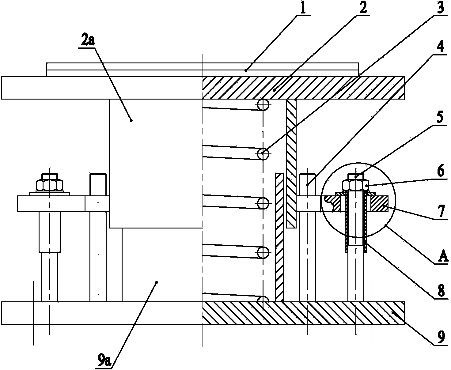
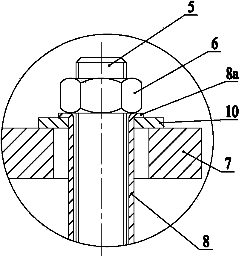
[0021] As shown in the figure: the field adjustable spring bracket in the embodiment is mainly composed of the top sliding pair 1, the upper bracket 2 of the spring bracket, the working spring 3, the lower bracket 9 of the spring bracket and the load preload value adjustment mechanism. The top sliding pair 1 is installed on the top of the bracket 2 on the spring bracket, and the top sliding pair 1 is used to be arranged under the pipe bracket to provide support for the pipe bracket and the pipeline. The pipe bracket and the pipeline can be placed on the top sliding pair 1 Move horizontally; the bottom surface of the upper bracket 2 of the spring bracket is provided with a vertically downward lower sleeve 2a, the lower bracket 9 of the spring bracket is arranged under the upper bracket 2 of the spring bracket, and the spring A vertically upward upper sleeve 9a i...


PUM


Abstract

The invention relates to a spring bracket allowing on-spot adjustment. A top sliding pair is installed on the top of a spring bracket upper strut and used for supporting a pipeline holder and a pipeline. A vertically-downward lower sleeve is arranged on the bottom face of the spring bracket upper strut. A spring bracket lower strut is arranged below the spring bracket upper strut. A vertically-upward upper sleeve is arranged on the top face of the spring bracket lower strut. The upper sleeve is sleeved with the lower sleeve. A working spring is arranged in the upper sleeve. The upper end of the working spring abuts against the bottom face of the spring bracket upper strut, and the lower end of the working spring is pressed on the top face of the spring bracket lower strut. The spring bracket upper strut and the spring bracket lower strut are connected through a load preloading value adjusting mechanism and can move vertically relative to each other. The spring bracket allowing on-spot adjustment is simple in structure and indigenous in design; compared with a spring bracket of the same type, the spring bracket allowing on-spot adjustment is more stable in performance and more convenient to construct and install, and meets design requirements better in actual working performance, thereby being capable of guaranteeing long-term and safe operation of a pipeline.

Description

technical field [0001] The invention relates to supporting parts of a pipeline equipment supporting device, in particular to a field adjustable spring bracket. Background technique [0002] At present, in order to ensure the safe use of high-temperature and high-pressure pipelines and solve the problem of weight loss caused by the vertical displacement of high-temperature and high-pressure pipelines, spring brackets are generally used for high-temperature and high-pressure pipeline equipment brackets to support pipelines and meet the vertical thermal displacement requirements of high-temperature and high-pressure pipelines , but it mainly has the following defects: [0003] (1) The spring preload in the existing spring bracket must be completed in the equipment manufacturer, and the preloaded spring cannot be adjusted according to the site conditions at the construction site. [0004] (2) Due to the large deviation between the calculated weight of the pipeline design and th...

Claims


Application Information

Patent Timeline
Patent Type & Authority Applications(China)
IPC IPC(8): F16L3/205
CPCF16L3/2056
Inventor 周致中
Owner JIANGSU MINGJIANG MACHINERY MFG
Why Eureka
Try Eureka