Mechanical equipment and its air conditioning system

A technology for air-conditioning systems and mechanical equipment, applied in the fields of mechanical equipment and air-conditioning systems, can solve problems such as unsolvable problems, pollution, and impact on compressor life, and achieve the effects of avoiding pollution, ensuring heating effect, and ensuring service life.

Active Publication Date: 2018-02-09
HANGZHOU SANHUA RES INST CO LTD
View PDF7 Cites 0 Cited by
  • Summary
  • Abstract
  • Description
  • Claims
  • Application Information

AI Technical Summary

Problems solved by technology

[0007] First, the indoor unit is installed on the side wall of the control room, which affects the space and vision of the operator
[0008] Second, when the tower crane is disassembled and moved, it is necessary to remove the connecting pipeline between the air-conditioning indoor unit and the outdoor unit
Ordinary technicians cannot complete the removal and installation of the air conditioner. If the operation is not standardized, it may cause damage to the air conditioner; and if the refrigerant is directly discharged into the atmosphere during the disassembly process, it will cause certain pollution
[0009] Third, the lubricating oil in the compressor will be taken away when the refrigerant is recovered or discharged, which not only affects the life of the compressor, but also affects the cooling or heating effect of the air conditioning system
[0010] Fourth, when the outside temperature is lower than zero degrees Celsius, the efficiency of heat pump heating will be greatly reduced, and even the air conditioning system cannot be started and heating cannot be performed, so the heating effect of the split wall-mounted air conditioner is not good.
[0012] When the above-mentioned integrated locomotive air conditioner is used in the tower crane control room, it can obviously solve the above-mentioned first, second and third defects relatively easily, but it still cannot solve the above-mentioned fourth defect

Method used


Image

  • Mechanical equipment and its air conditioning system
  • Mechanical equipment and its air conditioning system
  • Mechanical equipment and its air conditioning system

Examples


Embodiment Construction

[0053] The core of the present invention is to provide an air-conditioning system. The structure design of the air-conditioning system has excellent heating performance even when the external environment temperature is low, so as to ensure the exertion of the heating effect. In addition, another core of the present invention is to provide a mechanical device including the above-mentioned air-conditioning system.

[0054] In order to enable those skilled in the art to better understand the technical solutions of the present invention, the present invention will be further described in detail below in conjunction with the accompanying drawings and specific embodiments.

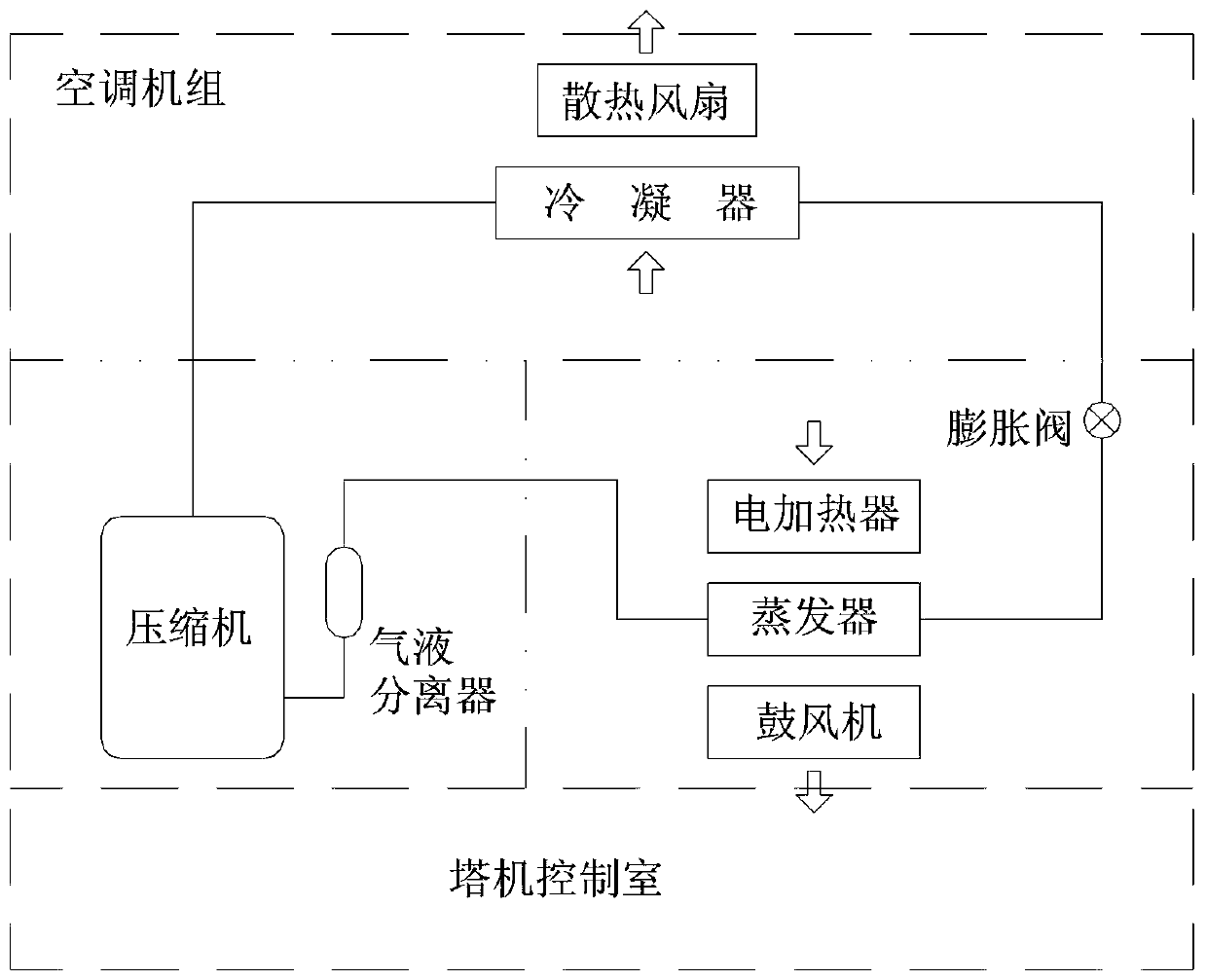
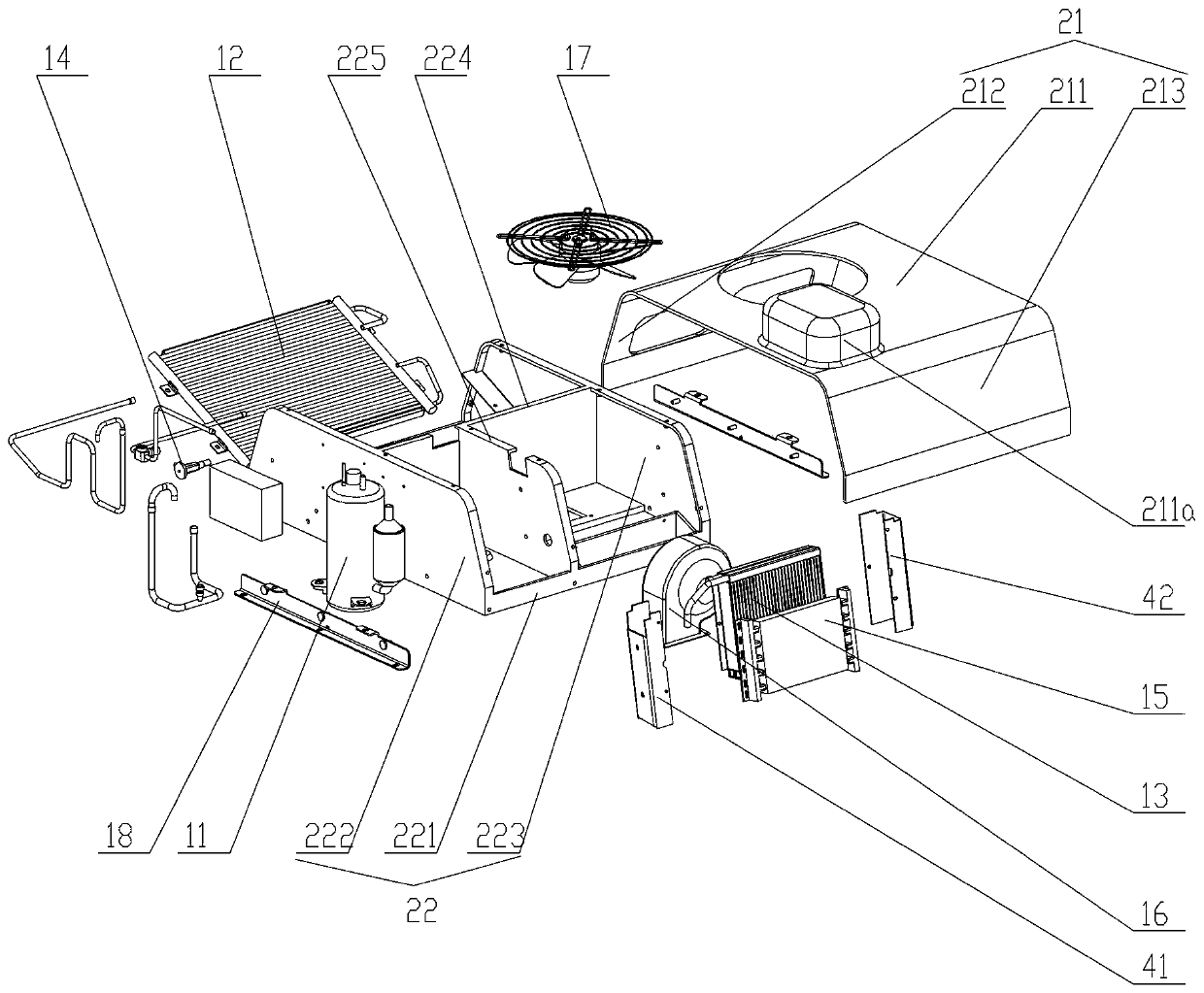
[0055] Please refer to figure 2 , image 3 and Figure 4 , figure 2 It is a schematic diagram of the principle of the air-conditioning system in an embodiment of the present invention; image 3 for figure 2 Structural explosion diagram of the central air-conditioning system; Figure 4 for image 3 The ...


PUM


Abstract

The invention discloses an air-conditioning system, which comprises an air-conditioning casing fixedly arranged on the outer wall of the working chamber, a compressor (11), a condenser (12), and a compressor (11) fixedly arranged in the air-conditioning casing. An evaporator (13) and a throttling element (14); the air-conditioning system also includes a first air guiding channel and a second air guiding channel; the air-conditioning system also includes a heater (15) fixed in the air-conditioning housing , so that when heating, the first air guiding channel absorbs the cold air in the working room, and the cold air passes through the heater (15) to exchange heat to form hot air, and then the hot air enters the working room through the second air guiding channel for heating. The structural design of the air conditioning system also has excellent heating performance when the external ambient temperature is low, thereby ensuring the heating effect to be exerted. In addition, the present invention also discloses a mechanical device including the above-mentioned air-conditioning system.

Description

technical field [0001] The invention relates to the technical field of refrigeration and heating, in particular to an air conditioning system. Furthermore, the invention also relates to a machine comprising the air conditioning system. Background technique [0002] Tower crane is an important mechanical equipment in engineering construction, and its key part is the control room. Due to the need for high-altitude operations, operators have high requirements for the three-dimensional vision of the tower crane control room, so the volume of the tower crane control room is very small, generally only one operator is allowed in the space, and the front and left and right sides of the operator are at the same time The glass is embedded to maximize the operator's vision, which makes the heat insulation and heat preservation performance of the control room poor, and the operator has a strong sense of temperature in summer and winter, so it is urgent to provide a system that can neit...

Claims


Application Information

Patent Timeline
Patent Type & Authority Patents(China)
IPC IPC(8): F24F1/00F24F13/20B66C13/52
Inventor 叶克利
Owner HANGZHOU SANHUA RES INST CO LTD
Why Eureka
Try Eureka