
Biological signal measuring system and method

A biological signal and measurement system technology, applied in the field of biological signal measurement systems that can improve the accuracy of biological signal measurement, can solve the problems of sensing signal interference, weak bioelectrical signals, and affecting optical sensors to obtain PPG signals, etc., to achieve The effect of ensuring accuracy

Active Publication Date: 2016-11-23
FUGANG ELECTRONICS KUNSHAN +1
View PDF5 Cites 1 Cited by
  • Summary
  • Abstract
  • Description
  • Claims
  • Application Information

AI Technical Summary

Problems solved by technology

[0003] However, for biosignal measurement devices based on light sensors, the manufacturing materials have an impact on the transmittance of human skin, such as the main material is easy to absorb light, etc. In addition, due to the influence of ambient light and ultraviolet rays, it is easy to cause sensing The signal is disturbed, therefore, the interference of ambient light will affect the light sensor to obtain the PPG signal and ultimately affect the accuracy of heart rate variation detection
Moreover, for a biosignal measurement device based on a bioimpedance sensor, the bioelectrical signal of the bioimpedance sensor is extremely weak, and is extremely susceptible to interference from ambient light and ultraviolet rays.

Method used


Image

  • Biological signal measuring system and method
  • Biological signal measuring system and method

Examples


Embodiment Construction

[0028] In order to describe the technical content, structural features, achieved goals and effects of the present invention in detail, the following will be described in detail in conjunction with the embodiments and accompanying drawings.

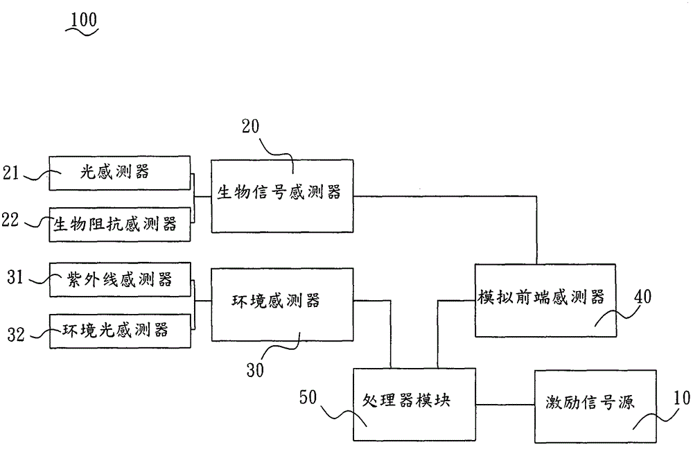
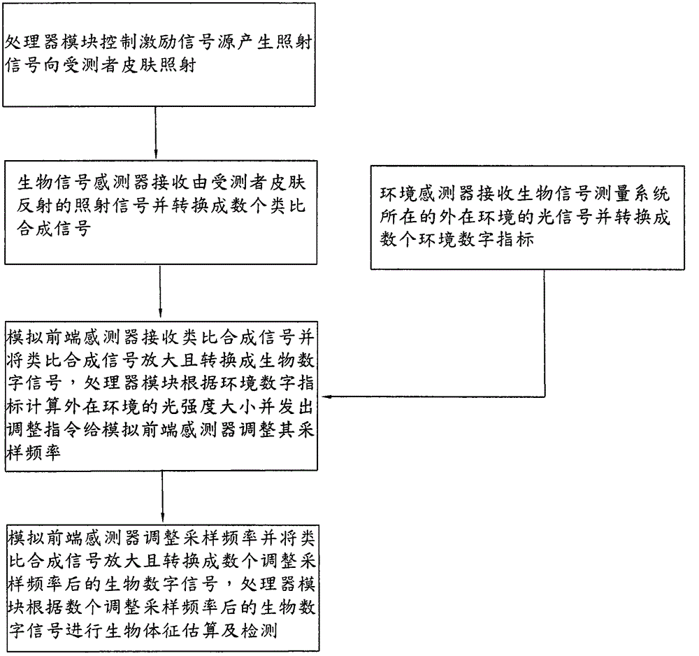
[0029] see figure 1 and figure 2 , a biosignal measurement system 100 of the present invention includes an excitation signal source 10 , a biosignal sensor 20 , an environment sensor 30 , an analog front-end sensor 40 and a processor module 50 .

[0030] The processor module 50 controls the excitation signal source 10 to generate an illumination signal to transmit to the skin of the subject and irradiate different areas respectively, so that the light source penetrates the skin and is reflected by the skin of the subject. Specifically, the excitation signal source 10 generates light signals or bioelectric pulse signals to irradiate the skin of the subject.

[0031] The biological signal sensor 20 receives the irradiation signal reflecte...


PUM


Abstract

The invention discloses a biological signal measuring system which comprises an exciting signal source, a biological signal sensor, an environment sensor, an analog front end sensor and a processor module. The exciting signal source generates irradiation signals to irradiate skin of a testee. The biological signal sensor receives irradiation signals reflected by the skin of the testee and converts the irradiation signals into a plurality of analog complexing signals. The environment sensor receives light signals of an external environment and converts the light signals into a plurality of environment digital indexes. The analog front end sensor receives and amplifies the analog complexing signals and converts the analog complexing signals into biological digital signals. The processor module is electrically connected to the exciting signal source, the environment sensor, the biological signal sensor and the analog front end sensor, calculates the light intensity of the external environment according to the environment digital indexes, sends out an adjusting instruction to the analog front end sensor to adjust the sampling frequency of the analog front end sensor, and estimating and detecting the biological sign according to the biological digital signals collected after the sampling frequency is adjusted. In conclusion, the biological signal measuring system is high in measuring accuracy.

Description

technical field [0001] The invention relates to a biological signal measurement system, in particular to a biological signal measurement system and method capable of improving the accuracy of biological signal measurement. Background technique [0002] Conventional biological signal measurement devices for detecting heart rate variability, such as earphones and wristbands, include a main body, a light source, a light sensor or a bio-impedance sensor. The light is reflected by the light source into the subject's skin, and then the light sensor senses the change of the reflected light over a period of time to obtain the photoplethysmography (PPG) signal, so as to detect the variation of heart rate through the signal sex. [0003] However, for biosignal measurement devices based on light sensors, the manufacturing materials have an impact on the transmittance of human skin, such as the main material is easy to absorb light, etc. In addition, due to the influence of ambient lig...

Claims


Application Information

Patent Timeline
IPC IPC(8): A61B5/0245
Inventor 李政吴国扬许文彬钟享陵
Owner FUGANG ELECTRONICS KUNSHAN
Learn More