Method and device for detecting vehicle failure
A technology of automobile faults and detection methods, applied in the field of automobiles, can solve problems such as inability to accurately locate faults and unfavorable maintenance work.
- Summary
- Abstract
- Description
- Claims
- Application Information
AI Technical Summary
Problems solved by technology
Method used
Image
Examples
Embodiment 1
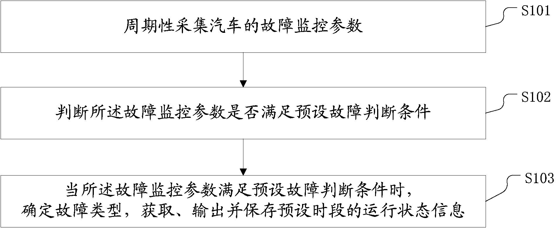
[0073] figure 1 It is a flow chart of an automobile fault detection method disclosed in the embodiment of the present application.
[0074] Such as figure 1 As shown, the fault detection method disclosed in Embodiment 1 includes the following steps:
[0075] S101: collecting fault monitoring parameters of the vehicle;
[0076] The above fault monitoring parameters include engine speed, vehicle water temperature, driving speed or engine oil pressure, etc. By detecting and judging different fault monitoring parameters, different types of fault detection can be realized.
[0077] S102: judging whether the fault monitoring parameters meet a preset fault judging condition;
[0078] S103: When the fault monitoring parameter satisfies a preset fault judgment condition, determine the fault type, acquire, output, and save the operation state information for a preset period of time.
[0079] The running status information of the above preset period includes the engine speed, driving...
Embodiment 2
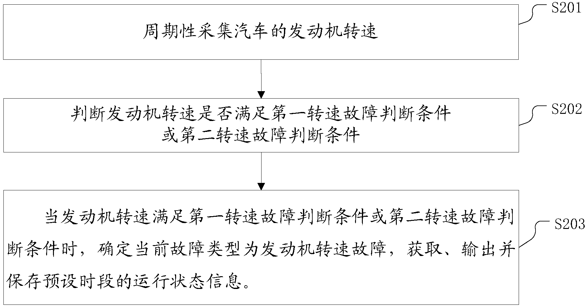
[0083] figure 2 It is a flow chart of an automobile fault detection method disclosed in Embodiment 2 of the present application.
[0084] Such as figure 2 As shown, the automobile fault detection method disclosed in the second embodiment includes the following steps:
[0085] S201: Periodically collect the engine speed of the vehicle;
[0086] The acquisition method is periodic sampling, and the sampling period is preferably 100 milliseconds.
[0087] S202: Determine whether the engine speed meets the first speed failure judgment condition or the second speed failure judgment condition;
[0088] The first speed failure judgment condition includes: the actual speed drop value of the engine speed is greater than the preset speed drop value in two consecutive sampling periods, and the engine speed is less than Preset minimum speed.
[0089] The actual speed drop value mentioned here refers to the decrease value of the engine speed per unit time when the engine is running, ...
Embodiment 3
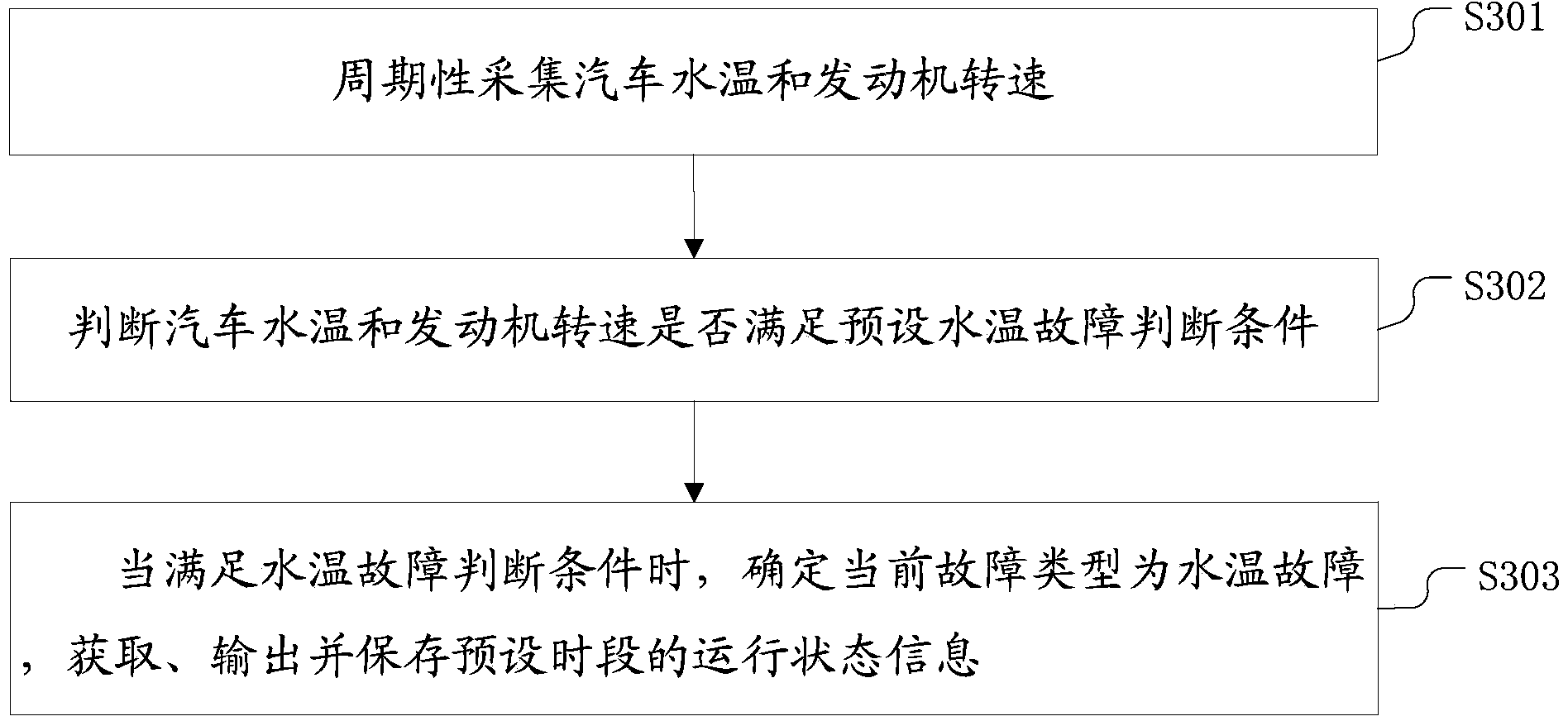
[0102] image 3 It is a flow chart of an automobile fault detection method disclosed in Embodiment 3 of the present application.
[0103] Such as image 3 As shown, the automobile fault detection method disclosed in the third embodiment includes the following steps:
[0104] S301: Periodically collect vehicle water temperature and engine speed;
[0105] The acquisition method is periodic sampling, and the sampling period is preferably 100 milliseconds.
[0106] S302: judging whether the vehicle water temperature and engine speed meet the preset water temperature fault judging conditions;
[0107] The conditions for judging a water temperature fault include: within n consecutive sampling periods, the vehicle's water temperature is higher than a preset water temperature, and the engine speed is higher than a second preset maximum speed, where n is a positive integer.
[0108] S303: When the vehicle water temperature and engine speed meet the water temperature fault judging c...
PUM
 Abstract
Description
Claims
Application Information
 - R&D
- Intellectual Property
- Life Sciences
- Materials
- Tech Scout
- Unparalleled Data Quality
- Higher Quality Content
- 60% Fewer Hallucinations
Browse by: Latest US Patents, China's latest patents, Technical Efficacy Thesaurus, Application Domain, Technology Topic, Popular Technical Reports.
© 2025 PatSnap. All rights reserved.Legal|Privacy policy|Modern Slavery Act Transparency Statement|Sitemap|About US| Contact US: help@patsnap.com


