Flexible power transmission device

A power transmission device, flexible technology, applied in the field of transmission, to achieve the effect of simple adjustment, accurate axial positioning, and reduction of dynamic load interference

Active Publication Date: 2014-01-22
芜湖铭信电机节能科技有限公司
View PDF8 Cites 10 Cited by
  • Summary
  • Abstract
  • Description
  • Claims
  • Application Information

AI Technical Summary

Problems solved by technology

[0009] Aiming at the adjustment problem of flexible power transmission, the present invention proposes a flexible power transmission device to solve t

Method used


Image

  • Flexible power transmission device
  • Flexible power transmission device
  • Flexible power transmission device

Examples


Embodiment Construction

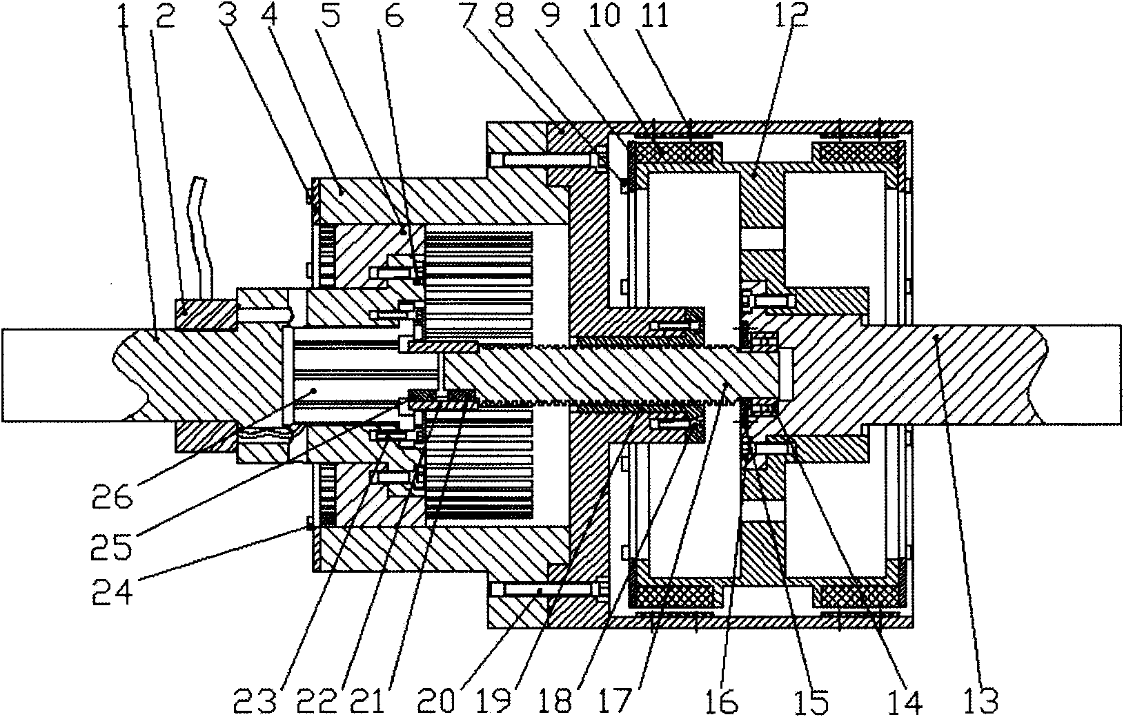
[0032] As shown in the figure, a flexible power transmission device includes an input device, an output device and an adjustment device. The input device includes an input shaft 1, a conductor barrel 7, and a conductor ring 11; the adjustment device includes a spline 5, a spline sleeve 4, a motor 26, a threaded rod 17, and a nut 19; the output device includes a permanent magnet 10, a permanent magnet barrel 12, an output axis. The section of the input shaft 1 is stepped, and one end of the input shaft 1 ( figure 1in the left) is connected to the transmission. The spline 5 is cylindrical, and splines are evenly distributed on the outer surface of the cylinder. The spline 5 is connected with the other end of the input shaft 1. The spline 5 is set on the input shaft 1, and the spline The key 5 is fixedly installed on the input shaft 1. The spline sleeve 4 is also cylindrical, and the inner surface of the spline sleeve 4 is evenly distributed with spline grooves corresponding t...


PUM


Abstract

A flexible power transmission device comprises an input shaft, a conductor cylinder, conductor rings, a permanent magnet cylinder, permanent magnets, an output shaft, a spline and a spline hub, wherein the conductor rings are mounted on the inner wall of the conductor cylinder; the permanent magnets are mounted on the outer wall of the permanent magnet cylinder; an air gap is formed between each permanent magnet and each conductor ring; the permanent magnet cylinder is connected with the output shaft; the spline is connected with the input shaft; the spline hub is connected with the conductor cylinder; and the spline is connected with the spline hub. Compared with the prior art, the device synchronously rotates with other parts, and the conductor cylinder is driven to regulate the flexible power transmission, so that dynamic load interference caused by change of speed difference during regulating of a load device is reduced, and the regulation becomes simple, stable and efficient.

Description

technical field [0001] The patent of the present invention belongs to the technical field of transmission, and in particular relates to a power transmission device. Background technique [0002] At present, the power transmission device is mainly a mechanical transmission system. The mechanical transmission system can be mainly divided into mechanical rigid transmission mode and mechanical flexible transmission mode. [0003] Mechanical rigid transmission mainly includes various types of mechanical couplings, which have the advantage of being able to realize synchronous transmission and high transmission efficiency. However, the mechanical rigid transmission method has high requirements on the alignment of the motor shaft and the load shaft, and its service life is often affected by vibration and wear. For large-scale equipment or high-precision transmission systems, it is very difficult to install on the center. Once there is an error in the centering, the transmission sy...

Claims


Application Information

Patent Timeline
IPC IPC(8): H02K51/00
CPCH02K49/06
Inventor 殷秀银
Owner 芜湖铭信电机节能科技有限公司
Why Eureka
Try Eureka