
IGBT (Insulated Gate Bipolar Transistor) driving circuit with dead zone adjustment
A driving circuit and dead zone adjustment technology, applied in the direction of electrical components, output power conversion devices, etc., can solve the problems of device turn-on and turn-off, delay, etc., to avoid shoot-through, improve reliability, and low cost.
- Summary
- Abstract
- Description
- Claims
- Application Information
AI Technical Summary
Problems solved by technology
Method used
Image

Examples
Embodiment Construction
[0008] The specific implementation manner of the present invention will be further described below in conjunction with the accompanying drawings.
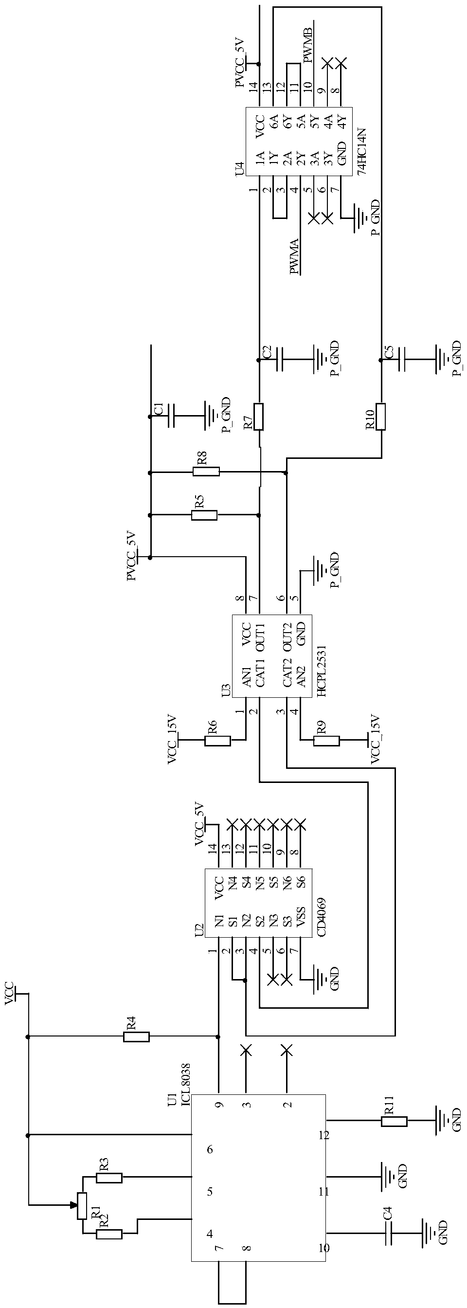
[0009] Such as figure 1 As shown, an IGBT drive circuit with dead zone adjustment includes a sliding rheostat R1, a first resistor R2, a second resistor R3, a third resistor R4, a fourth resistor R5, a fifth resistor R6, a sixth resistor R7, a Seventh resistor R8, eighth resistor R9, ninth resistor R10, tenth resistor R11, first capacitor C1, second capacitor C2, third capacitor C3, fourth capacitor C4, fifth capacitor C5, square wave generator U1 ( ICL8038), inverter U2 (CD4069), optocoupler U3 (HCPL2531), Schmitt inverter U4 (74HC14N).
[0010] Pin 7 of the square wave generator U1 is connected to pin 8, pin 4 of the square wave generator U1 is connected to one end of the first resistor R2, and the other end of the first resistor R2 is connected to a fixed end of the sliding rheostat R1, The sliding end of the sliding rheos...
PUM
 Abstract
Description
Claims
Application Information