
Video data decoding method and video data decoding apparatus

A technology of video data and decoding method, which is applied in the field of video data decoding and equipment, and can solve problems such as video damage, P frame damage, and destruction

Inactive Publication Date: 2014-01-22
HYUNDAI MOBIS CO LTD
View PDF4 Cites 0 Cited by
  • Summary
  • Abstract
  • Description
  • Claims
  • Application Information

AI Technical Summary

Problems solved by technology

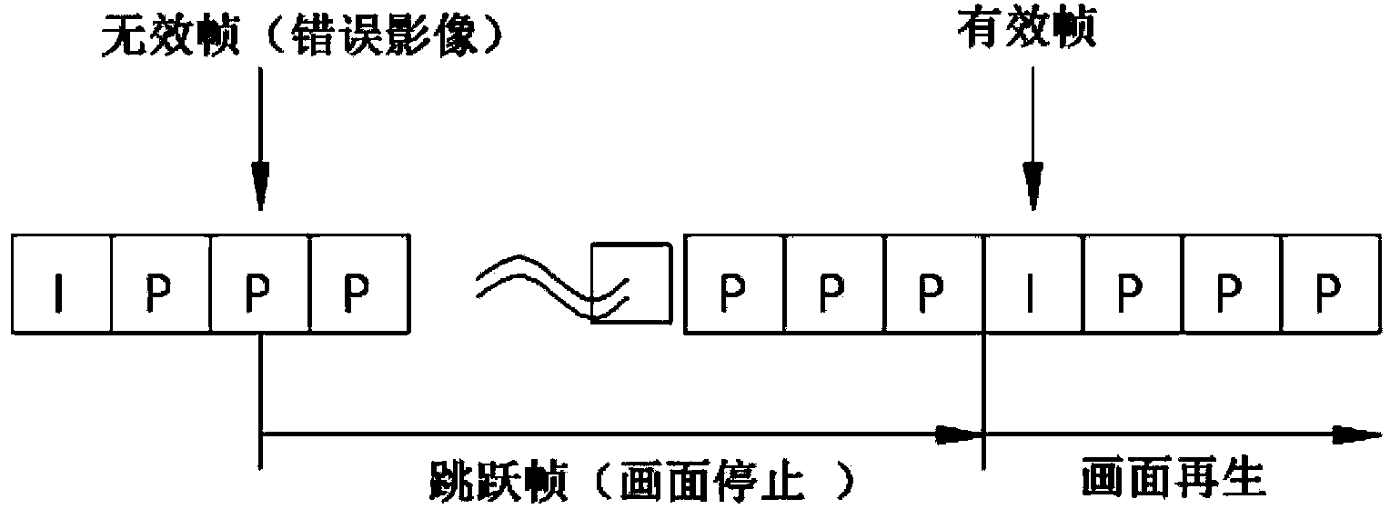
However, the P4 frame cannot be received normally and the e video frame cannot be generated. When the e video frame cannot be generated, even if the P5 frame can be received normally, the f video frame and subsequent video frames cannot be generated.
[0008] image 3 It is a video description generated when the P frame cannot be received normally. The damaged P frame cannot generate a video frame before the new I frame that appears later, so the picture will temporarily stop or be destroyed.
[0009] Same as above, in the previous video data decoding method, the P frame received from the weak current world will be damaged. Even if only one P frame is damaged, the video will be damaged before the new I frame appears.

Method used


Image

  • Video data decoding method and video data decoding apparatus
  • Video data decoding method and video data decoding apparatus
  • Video data decoding method and video data decoding apparatus

Examples


Embodiment Construction

[0030] The advantages and features of the present invention, as well as the method for achieving them will become very clear with reference to the drawings and detailed embodiments described later. However, the present invention is not limited to the following embodiments, and various forms different from each other can be realized, but in order to present the embodiments of the present invention more completely, to provide a more complete scope of the present invention to those skilled in the art to which the present invention belongs, the present invention According to the category definition of the claim.

[0031] In addition, the terminology used in this specification is for describing an Example, and it does not limit this invention. Sentences in this specification do not specifically refer to singular forms, but plural forms may also be included. The terms "comprises" and / or "comprising" used in the specification refer to constituent elements, stages, actions and / or ele...


PUM


Abstract

The invention relates to a video data decoding method and a video data decoding apparatus. According to the method and apparatus, if the signal reception condition is poor and fault frames are generated, the fault frames are derived and created based on a normally-received frame in adjacent frames, thereby preventing the pulse and rupture of the regenerated video.

Description

technical field [0001] The present invention is a decoding method and equipment for receiving video data signals and using I frames and P frames contained in the data signals to generate video data of video frames, and more specifically, the frames are damaged due to poor reception status of video data signals. case, repair corrupted frames and prevent video corruption from occurring. Background technique [0002] When transmitting video data, the amount of data is too large if each video frame itself is directly transmitted, and the P frame after the variation between the I frame and each video frame is extracted is used for transmission, and the video data signal is received in the I frame The P frames are superimposed in order to generate video frames and then a video is generated. [0003] figure 1 It is a schematic diagram of the conventional video data signal receiving and decoding sequence. [0004] The video data decoding device does not distinguish a video frame,...

Claims


Application Information

Patent Timeline
Patent Type & Authority Applications(China)
IPC IPC(8): H04N19/50H04N19/159
CPCH04N19/102H04N19/177H04N19/50
Inventor 李庸俊
Owner HYUNDAI MOBIS CO LTD
Learn More