
Polygonal counter flow cooling tower

A cooling tower and counter-flow technology, applied in the field of cooling towers, can solve the problems of large air outlet resistance coefficient, large power consumption, occupying installation area, etc., and achieve the effect of improving thermal performance efficiency, enhancing stability performance, and increasing supporting points.

Inactive Publication Date: 2012-10-31
南京大洋冷却塔股份有限公司
View PDF0 Cites 0 Cited by
  • Summary
  • Abstract
  • Description
  • Claims
  • Application Information

AI Technical Summary

Problems solved by technology

The appearance of the square counterflow cooling tower does not match the modern buildings, which affects the visual effect
The umbrella film formed by the splashing water of the water distribution nozzle is larger, the hollow area is larger, the water droplets are thicker and the distribution of the splashing water is uneven, resulting in high energy consumption (large power consumption) and low efficiency of the fan
Most of the air ducts are simple and straight, the air inlet is not smooth, and the resistance coefficient of the air outlet is large, which increases the power consumption of the fan
These have caused the overall thermal performance of the cooling tower to be low (cooling effect), which cannot meet the national standard
[0005] Circular counter-flow cooling tower has low thermal performance efficiency and high floating water rate, which cannot meet the national standard
The appearance is not beautiful, and it belongs to the oldest generation of towers. It is not beautiful in appearance when it matches with modern buildings; it cannot be assembled and used by multiple units, and it occupies the installation area; to customer request)

Method used


Image

  • Polygonal counter flow cooling tower
  • Polygonal counter flow cooling tower
  • Polygonal counter flow cooling tower

Examples


Embodiment Construction

[0047] The present invention will be further described below in conjunction with the accompanying drawings and specific embodiments.

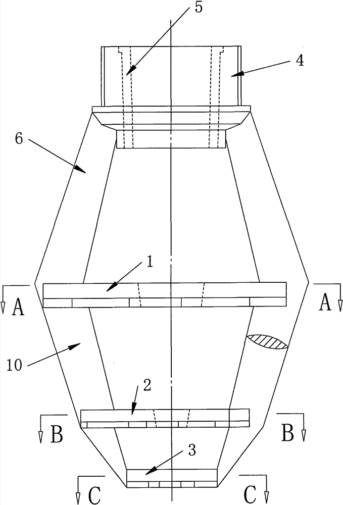
[0048] see Figure 11 , 12 The polygonal counter-flow cooling tower shown has a frame 11 whose periphery is a regular octagon. A frame 27 is arranged on the top of the frame, and an air duct 12 is arranged on the frame 27 . see Figure 21 , the air duct has a diffusion section 121, a working section 122, and an air inlet section 123 from top to bottom. . The foundation pier 20 supports the frame 11, and the motor 21 is connected with the fan through the shaft of the transmission mechanism. A ladder 28 is provided outside the frame.

[0049] The upper periphery of the frame has wall panels 14 , and the lower periphery of the frame has air inlet windows 30 . The frame inside the wallboard is provided with a water-drinking filler 15 composed of a plurality of spaced filler sheets. The water shower filler 15 is placed on the filler bracket ...


PUM


Abstract

The invention provides a polygonal counter flow cooling tower which has small ventilation resistance, favorable thermal performance and low energy consumption and can be completely combined with a building. The polygonal counter flow cooling tower comprises a framework, an air duct arranged at the top of the framework and a blower arranged in the air duct; wall boards are arranged on the periphery at the upper part of the framework; air inlet windows are arranged on the periphery at the lower part of the framework; packing comprising a plurality of alternate filler pieces is arranged in the frames of the wall boards; a water distribution pipe is arranged above the packing; a water distribution spray head for spraying water into clearances among the filler pieces is arranged at the bottom of the water distribution pipe; a water collector is arranged above the water distribution pipe; a reception basin is arranged at the bottom of the framework and supported by a bottom beam; a water outlet is arranged at the lower part of the reception basin; and the periphery of the framework is octagonal.

Description

technical field [0001] The invention relates to a central air conditioner and a cooling tower for industrial circulating water. Background technique [0002] At present, all central air-conditioning process circulating water systems and industrial process circulating water systems are equipped with counter-flow cooling towers. It includes a frame, an air duct installed on the frame at the top of the frame, and a fan installed in the air duct; the upper periphery of the frame has a wall panel, the lower periphery of the frame has an air inlet window, and the frame inside the wall panel is provided with a The water spraying packing is composed of multiple spaced packing sheets, and there is a water distribution pipe above the water spraying packing, and the bottom of the water distribution pipe is provided with a water distribution nozzle for spraying water into the gap between the packing sheets; above the water distribution pipe It has a water collector; the water collectio...

Claims


Application Information

Patent Timeline
Patent Type & Authority Patents(China)
IPC IPC(8): F28C1/02F28F25/06F28F25/04F28F25/10F28F25/00F28F25/08
Inventor 费笑勇史金华
Owner 南京大洋冷却塔股份有限公司
Learn More