
Rotary flow guide type air draft system of laser cutting machine

A laser cutting machine and ventilation system technology, applied in laser welding equipment, welding equipment, metal processing equipment, etc., can solve the problems of large ventilation resistance, high noise, and high energy consumption, and achieve low ventilation resistance, low noise, and high energy consumption. The effect of low consumption

Pending Publication Date: 2020-12-11
安徽东海裕祥智能装备科技有限公司
View PDF0 Cites 0 Cited by
  • Summary
  • Abstract
  • Description
  • Claims
  • Application Information

AI Technical Summary

Problems solved by technology

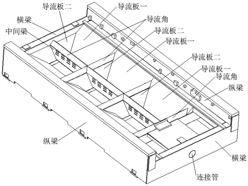
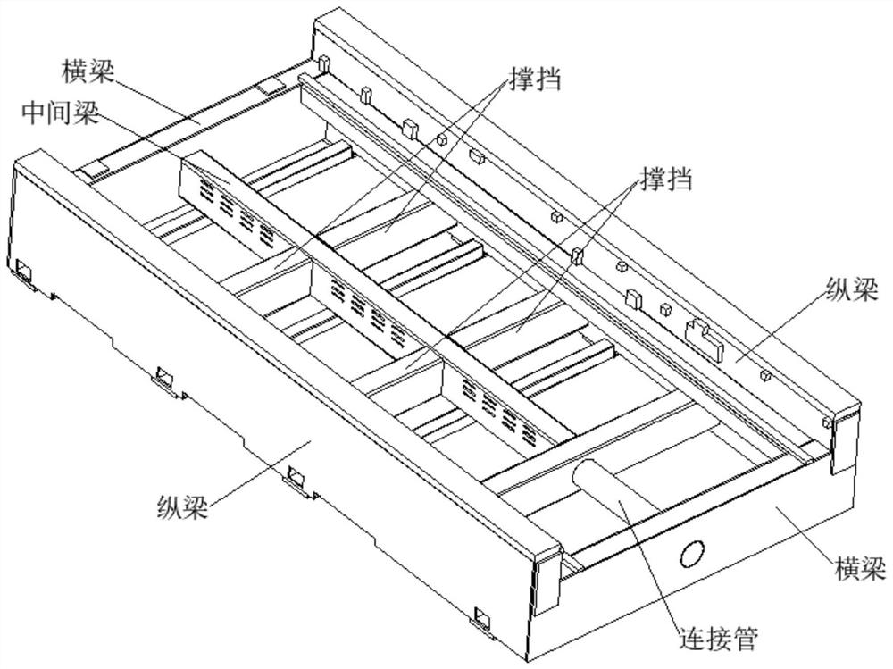
[0008] 1. Due to the multiple heat dissipation holes set on the middle beam, each section separated by the brace is in a normally open state, and segmental ventilation cannot be realized, so that the exhaust fan is always running at high load, with high energy consumption and high noise
[0009] 2. There is only one hollow middle beam set in the middle as the ventilation duct, and the single ventilation duct has low ventilation efficiency and poor heat dissipation effect
[0010] 3. The hot gas entering the middle beam from the heat dissipation holes on both sides of the middle beam at the same time collides, which makes the draft resistance large, and the exhaust fan needs to run at high load all the time, which consumes a lot of energy and makes a lot of noise

Method used


Image

  • Rotary flow guide type air draft system of laser cutting machine
  • Rotary flow guide type air draft system of laser cutting machine
  • Rotary flow guide type air draft system of laser cutting machine

Examples


Embodiment 1

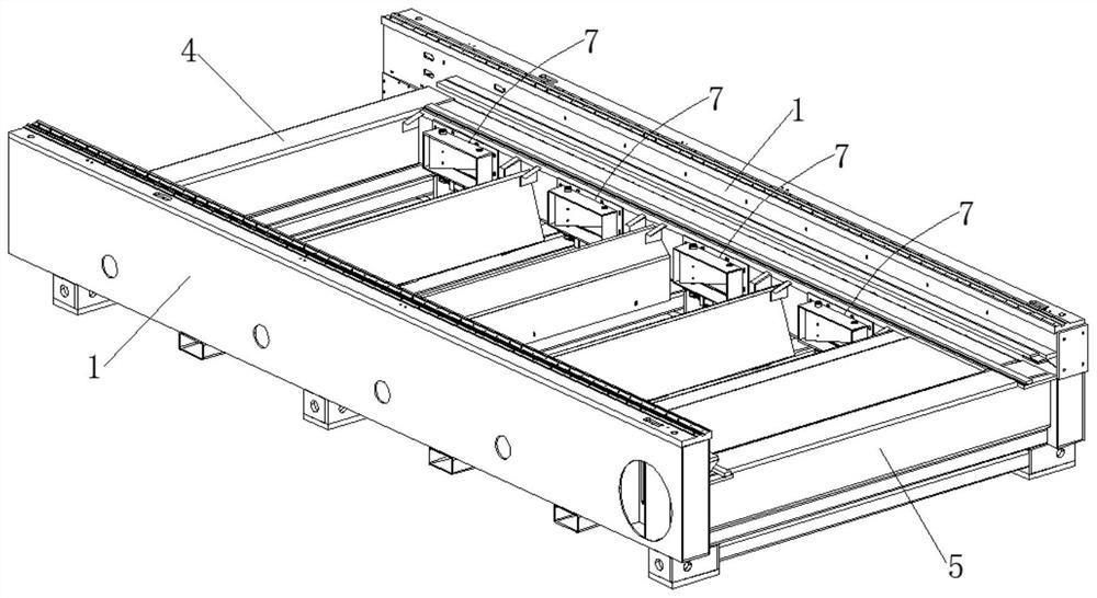
[0040] In the laser cutting machine rotary diversion type exhaust system, the left air guide pipe 2 is welded to the left longitudinal beam 1, the right air guide pipe 3 is welded to the right longitudinal beam 1, and the cross brace 4 The two ends are respectively welded to one end of the two longitudinal beams 1, and the two ends of the cross brace 5 are respectively welded to the other end of the two longitudinal beams 1, and communicated with the air outlet 10 on the longitudinal beam 1, and the left air guide pipe 2 The end of the right air guide pipe 3 is welded to the first 4 of the cross brace, and connected to the second 5 of the cross brace 5, and the exhaust operation is performed through the double exhaust air duct formed by the left air guide 2 and the right air guide 3, and the exhaust efficiency is improved. High, good cooling effect.

Embodiment 2

[0042] On the basis of Embodiment 1, a plurality of heat dissipation holes 2-1 are evenly spaced on the inner wall of the left air duct 2 and the right air duct 3, and the laser cutting machine is divided into multiple sections. During the cutting process, which section the light beam cuts to, the piston rod of the cylinder 72 in the rotary opening and closing mechanism 7 of this section shrinks, the connecting rod 73 rotates with the main shaft 74, and the main shaft 74 rotates with the sealing plate 75 to open, so that the outer The frame 70-2, the rectangular hole 70-1, and the heat dissipation hole 2-1 conduct, the piston rod of the other section cylinder 72 is in the extended state, the outer frame 70-2, the rectangular hole 70-1, and the heat dissipation hole 2-1 Closed, the segmental exhaust is realized, so that the exhaust fan operates at low load, with low energy consumption and low noise.

Embodiment 3

[0044] On the basis of Example 1, a large amount of hot gas generated by cutting is discharged in two ways, one way is outer frame 70-2-rectangular hole 70-1-heat dissipation hole 2-1-left air duct 2-horizontal block 2 5-exhaust fan, the other one is the outer frame 70-2-rectangular hole 70-1-radiation hole 2-1-right air duct 3-horizontal brace 2 5-exhaust fan, compared with the prior art, the hot gas from The heat dissipation holes on both sides of the middle beam enter the middle beam at the same time and collide. After opening, the sealing plate 75 is cut and located in the heat dissipation hole 2-1, which plays a role of drainage, with small draft resistance, low-load operation of the exhaust fan, low energy consumption, and low noise. Small.


PUM


Abstract

The invention discloses a rotary flow guide type air draft system of a laser cutting machine. The rotary flow guide type air draft system comprises longitudinal beams, a left air guide pipe, a right air guide pipe, a first cross brace, a second cross brace, bottom braces and rotary opening and closing mechanisms, wherein the left air guide pipe is welded to the left longitudinal beam, the right air guide pipe is welded to the right longitudinal beam, and the two ends of the first cross brace are respectively welded to one ends of the two longitudinal beams; the two ends of the second cross brace are welded to the other ends of the two longitudinal beams respectively and communicated with air draft openings in the longitudinal beams, the end of the left air guide pipe and the end of the right air guide pipe are welded to the first cross brace and communicated with the second cross brace, the two ends of the bottom braces are welded to the two longitudinal beams correspondingly, and therotary opening and closing mechanisms are connected with the left air guide pipe and the right air guide pipe. a double air draft air duct formed by the left air guide pipe and the right air guide pipe is used for carrying out air draft operation, so that the air draft efficiency is high, and the heat dissipation effect is good; and the segmented air draft is achieved, an air draft fan operates ata low load, the energy consumption is low, and the noise is low.

Description

technical field [0001] The invention belongs to the technical field of laser cutting machine, in particular, the invention relates to a rotary guide type exhaust system of a laser cutting machine. Background technique [0002] The principle of the laser cutting machine is: the heat input by the beam far exceeds the reflected, conducted or diffused part of the cut material, and the material is quickly heated to the vaporization temperature, and evaporates to form holes. [0003] As the beam moves linearly relative to the material, the holes are continuously formed into a slit with a very narrow width (such as about 0.1mm). The heat effect of trimming is very small, and there is basically no deformation of the workpiece. During the cutting process, auxiliary gas suitable for the material to be cut is also added. When cutting steel, oxygen must be used as an auxiliary gas to produce an exothermic chemical reaction with molten metal to oxidize the material, and at the same tim...

Claims


Application Information

Patent Timeline
Patent Type & Authority Applications(China)
IPC IPC(8): B23K26/70B23K26/14B23K26/38
CPCB23K26/703B23K26/14B23K26/38
Inventor 孙绵玉石贤林宋术丰
Owner 安徽东海裕祥智能装备科技有限公司
Learn More