Bearing arrangement with a back-up bearing, in particular for mounting the rapidly rotating shaft of a compressor

A technology for bearing devices and supporting shafts, which is applied in the direction of rotating bearings, shafts and bearings, rolling contact bearings, etc., and can solve problems such as damage to spare bearing forces

Inactive Publication Date: 2014-01-22
SCHAEFFLER TECH AG & CO KG
View PDF4 Cites 2 Cited by
  • Summary
  • Abstract
  • Description
  • Claims
  • Application Information

AI Technical Summary

Problems solved by technology

In this case very high forces which

Method used


Image

  • Bearing arrangement with a back-up bearing, in particular for mounting the rapidly rotating shaft of a compressor
  • Bearing arrangement with a back-up bearing, in particular for mounting the rapidly rotating shaft of a compressor
  • Bearing arrangement with a back-up bearing, in particular for mounting the rapidly rotating shaft of a compressor

Examples


Embodiment Construction

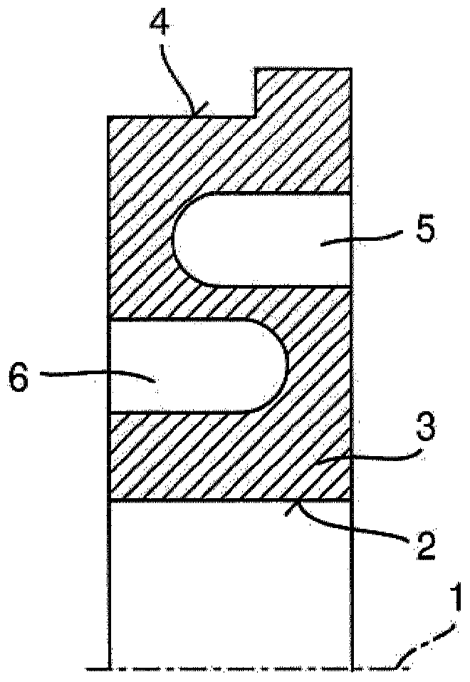
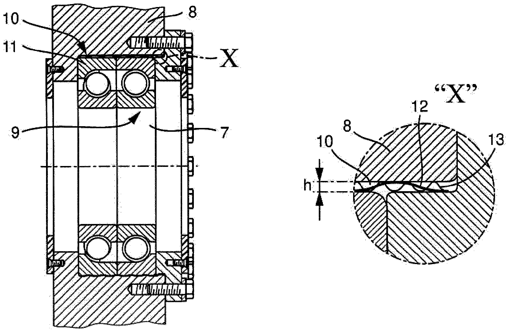
[0029] figure 1 A bearing arrangement is shown in which the shaft is mounted rotatably about the axis of rotation 1 by means of a magnetic bearing. The bearing arrangement includes at least one backup bearing, which is designed as a rolling bearing, in particular a double row angular contact ball bearing, and can absorb forces both in the axial direction and in the radial direction. The outer ring of the rolling bearing is arranged on the inner surface 2 of the bearing receptacle 3 pointing toward the axis of rotation 1 . The outer surface 4 of the bearing receptacle 3 is arranged on the stationary housing. As long as the shaft is mounted in a magnetic bearing, the inner ring of the rolling bearing is spaced from the peripheral side of the shaft by a backup bearing gap.

[0030] The bearing arrangement is part of the bearing of the shaft of the compressor, which rotates at a rotational speed of approximately 6000 revolutions per minute and is of solid design. If the magneti...


PUM


Abstract

The invention relates to a bearing arrangement for the rotatable mounting of a shaft (7) in relation to a housing (8), comprising a back-up bearing (9) which is designed as a rolling contact bearing, wherein the rolling contact bearing can absorb forces in the axial and radial direction and is designed in particular as an angular roller bearing, especially as a two-row angular ball bearing, wherein the rolling contact bearing (9) is substantially left open in the radial direction. The problem addressed by the invention is that of providing a bearing arrangement with a back-up bearing for a shaft, which bearing arrangement can better absorb in particular the forces occurring in the mounting of rapidly rotating, solid shafts.

Description

technical field [0001] The invention relates to a bearing arrangement with a backup bearing, in particular as part of a bearing of a rapidly rotating shaft of a compressor. Background technique [0002] Bearings are known in practice in which the shaft is mounted rotatably in, for example, magnetic bearings. The support mechanism includes a bearing arrangement with backup bearings, wherein at least one backup bearing accommodates the shaft if the magnetic bearing fails. During normal operation of at least one magnetic bearing, a backup bearing gap is formed between the peripheral side of the shaft and the peripheral side of the inner bearing ring of the backup bearing pointing toward the shaft. [0003] It is problematic to accommodate very fast rotating shafts of great weight in backup bearings in the event of failure of the magnetic bearing of the bearing, for example a solid shaft of a compressor which rotates at up to approximately 6000 revolutions per minute. In this ...

Claims


Application Information

Patent Timeline
IPC IPC(8): F16C27/04F16C39/02F16C32/04
CPCF16C27/04F16C27/08F16C32/0442F16C39/02F16C35/077F16C19/163F16C19/542F16C2300/22F16C19/18F16C33/583
Inventor 斯特凡·鲁尔约尔格·鲍尔彼得·西贝克阿尔明·本德马克·杜齐亚克米歇尔·保施
Owner SCHAEFFLER TECH AG & CO KG
Why Eureka
Try Eureka