
Audio codec using noise synthesis during inactive phases

A technology of audio encoder and audio decoder, applied in the field of audio codec

Active Publication Date: 2014-01-22
FRAUNHOFER GESELLSCHAFT ZUR FOERDERUNG DER ANGEWANDTEN FORSCHUNG EV
View PDF5 Cites 4 Cited by
  • Summary
  • Abstract
  • Description
  • Claims
  • Application Information

AI Technical Summary

Problems solved by technology

[0004] Synthesized noise, on the other hand, must closely mimic real noise so that the synthesis is transparent to the user

Method used


Image

  • Audio codec using noise synthesis during inactive phases
  • Audio codec using noise synthesis during inactive phases
  • Audio codec using noise synthesis during inactive phases

Examples


Embodiment Construction

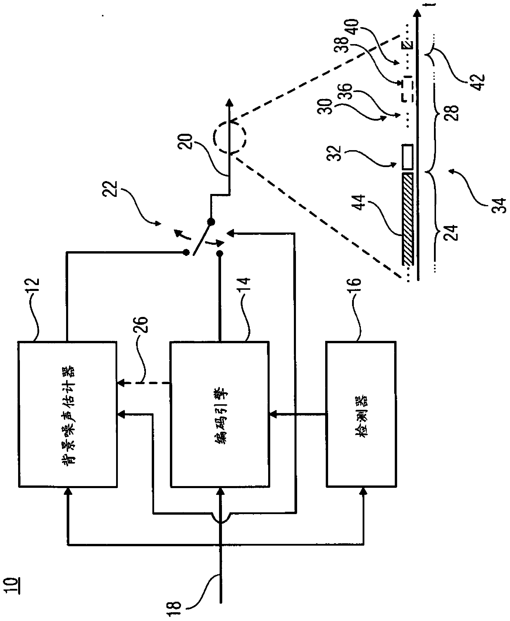
[0024] figure 1 An audio encoder according to an embodiment of the invention is shown. figure 1 The audio encoder includes a background noise estimator 12 , an encoding engine 14 , a detector 16 , an audio signal input 18 and a data stream output 20 . Provider 12 , encoding engine 14 and detector 16 each have an input connected to an audio signal input 18 . The output terminals of the estimator 12 and the encoding engine 14 are respectively connected to the data stream output terminal 20 via a switch 22 . The control inputs of the switch 22 , the estimator 12 and the encoding engine 14 are respectively connected to the output of the detector 16 .

[0025] The background noise estimator 12 is configured to continuously update the parametric background noise estimate during the active phase 24 based on the input audio signal entering the audio encoder 10 at the input 18 . Although figure 1 It is suggested that the background noise estimator 12 may derive continuous updates o...


PUM


Abstract

A parametric background noise estimate is continuously updated during an active or non-silence phase so that the noise generation may immediately be started with upon the entrance of an inactive phase following the active phase. In accordance with another aspect, a spectral domain is very efficiently used in order to parameterize the background noise thereby yielding a background noise synthesis which is more realistic and thus leads to a more transparent active to inactive phase switching.

Description

technical field [0001] The present invention relates to audio codecs supporting noise synthesis during periods of inactivity. Background technique [0002] It is known in the art to take advantage of periods of inactivity of speech or other noise sources to reduce transmission bandwidth. Such schemes typically use some form of detection to distinguish inactive (or silent) periods from active (or non-silent) periods. During periods of inactivity, lower bit rates are achieved by suspending the transmission of the normal data stream that exactly encodes the recorded signal and only sending Silent Insertion Description (SID) updates. SID updates may be transmitted at regular intervals, or when changes in background noise characteristics are detected. The SID frame can then be used on the decoding side to generate background noise whose characteristics are similar to the background noise during the active phase, so that suspending the transmission of the normal data stream enco...

Claims


Application Information

Patent Timeline
IPC IPC(8): G10L19/012
CPCG10L19/012G10L19/0212G10L19/04G10L19/18G10L25/84G10L19/00G10L19/005G10L19/025G10L19/028G10L19/08G10K11/16G10L19/02G10L19/03G10L19/07G10L19/10G10L19/107G10L19/12G10L19/13G10L19/22G10L21/0216G10L25/06G10L25/78G10L19/022G10L19/26
Inventor 帕尼·塞蒂亚万康斯坦丁·施密特斯特凡·维尔登
Owner FRAUNHOFER GESELLSCHAFT ZUR FOERDERUNG DER ANGEWANDTEN FORSCHUNG EV
Learn More