

Sliding rail assembling system and sliding rail assembling method using same
A slide rail assembly and slide rail technology, applied in metal processing, metal processing equipment, manufacturing tools, etc., can solve the problems of high cost, loose slide shaft rotation, unreliable connection, etc., and achieve low cost and fixed effect. Good results
- Summary
- Abstract
- Description
- Claims
- Application Information
AI Technical Summary
Problems solved by technology
Method used
Image

Examples
Embodiment Construction
[0031] The present invention will be described in detail below in conjunction with specific embodiments shown in the accompanying drawings. However, these embodiments do not limit the present invention, and any structural, method, or functional changes made by those skilled in the art according to these embodiments are included in the protection scope of the present invention.
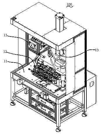
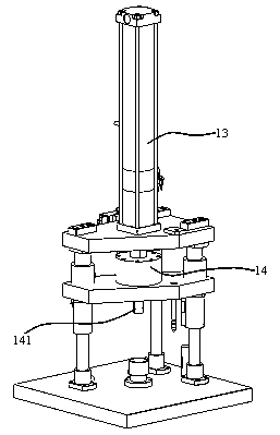
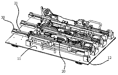
[0032] ginseng Figure 1 to Figure 3 , to introduce a specific embodiment of the slide rail assembly system 100 of the present invention, the slide rail assembly system 100 is used for installing the slide rail shaft 21 and the support member 30 . In this embodiment, the slide rail assembly system 100 includes a base 11 , a lifting mechanism 13 , a pressure sensor (not shown), a displacement sensor (not shown), and a controller (not shown).
[0033] The base platform 11 includes a station 12 for placing the automobile slide rail 20 , and the automobile slide rail 20 undergoes a series of subsequent pr...
PUM
 Abstract
Description
Claims
Application Information