Magic Wand Robot

A technology of robots and magic wands, applied in manipulators, program-controlled manipulators, manufacturing tools, etc., can solve problems such as lack of load capacity, limited use of snake-shaped robots, and inability of snake-shaped robots to carry loads, and achieve good stability and good performance. Effects of Terrain Adaptability and Surveillance Capabilities

Inactive Publication Date: 2016-08-17
SHANGHAI DIANJI UNIV
View PDF8 Cites 0 Cited by
  • Summary
  • Abstract
  • Description
  • Claims
  • Application Information

AI Technical Summary

Problems solved by technology

However, the snake-like robot with this structure does not have load capacity due to structural limitations, that is, the snake-like robot cannot carry heavy loads. This limitation limits the use of the snake-like robot

Method used


Image

  • Magic Wand Robot
  • Magic Wand Robot
  • Magic Wand Robot

Examples


Embodiment Construction

[0016] The following examples and attachments are combined Figure 1 to 3 The present invention will be further described.

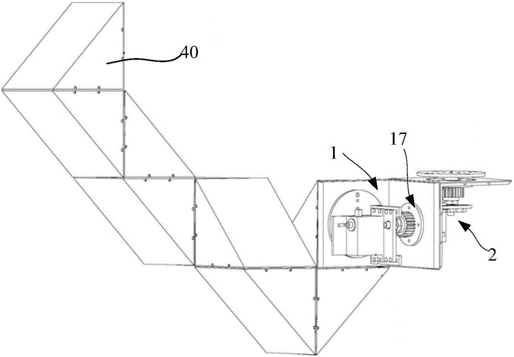
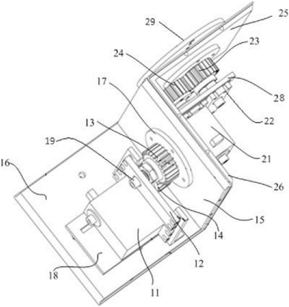
[0017] The present invention provides a magic wand robot, which includes multiple sets of drive units 40, and the drive units 40 are wedge-shaped and connected in series. figure 2 for figure 1 Part of the enlarged view, including figure 1 In the first drive unit 1 and the second drive unit 2, take the first drive unit 1 as an example. The first drive unit 1 includes a controller, a steering gear 11 that provides driving force, a bracket 18 that carries the steering gear 11, and a rudder The gears connected to the engine 11 and driven by the steering gear 11 to rotate, and the adjacent driving unit 40 can rotate under the driving of the second gear 13.

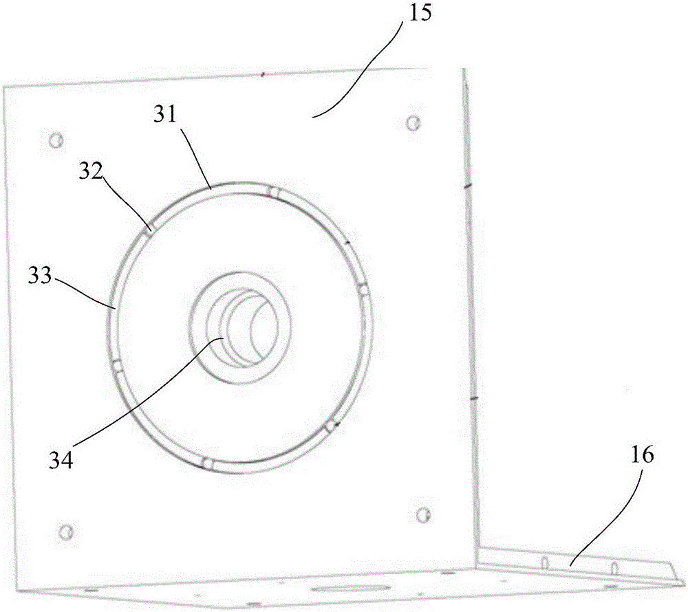
[0018] The first driving unit 1 also includes housings 15, 16 and housing covers. The controller, the steering gear 11, the central rotating body 19, the central rotating body fixing plate 12, the bracket 18 ...


PUM


Abstract

The present invention proposes a magic wand robot, which includes multiple sets of drive units, the drive units are wedge-shaped and connected in series, and the drive units include a controller, a steering gear that provides driving force, a bracket that carries the steering gear, and the drive unit. The steering gear is connected to and driven by the steering gear to rotate, and the adjacent driving unit can rotate under the driving of the gear. The magic wand robot of the present invention has good stability, can bear heavy loads, and can be used as special mechanical arms and intelligent brackets. After installing accessories such as miniature cameras and moving tools, it can have good terrain adaptability and monitoring capabilities. Work in environments with radiation, dust, and poison, and can also work in the ruins of earthquake landslides to perform reconnaissance missions.

Description

Technical field [0001] The invention relates to the field of mechanical manufacturing, and in particular to a magic wand robot. Background technique [0002] There has been a lot of research on snake-shaped robots in the prior art. For example, the patent application No. 02109369.5 discloses a snake-shaped robot. The snake-shaped robot is composed of a snake head, a snake tail, several node ends, a common wire spring, and a shape memory alloy. (SMA) The spring and the main components of the foot. The joint end and the joint end are connected by a common wire spring fixed on the joint end and four shape memory alloy (SMA) springs. The other joint ends are equipped with mechanisms that can control the foot extension and retraction. The control mechanism is composed of shape memory alloy (SMA) springs, connecting rods, spring sheets and slips installed at the end of the joint. According to the characteristics of the crawling ground, the foot can be equipped with rubber pads or meta...

Claims


Application Information

Patent Timeline
Patent Type & Authority Patents(China)
IPC IPC(8): B25J9/10B25J9/08
Inventor 黄瀛
Owner SHANGHAI DIANJI UNIV
Why Eureka
Try Eureka