Integrated tool-setting type numerical-control engraving machine portal frame assembly

A knife-shaped, integral technology, applied in engraving, processing models, decorative arts, etc., can solve problems such as unfavorable engraving accuracy, X-direction rail fatigue, short service life, etc., to improve walking accuracy and engraving accuracy, and high work efficiency. Effect

Inactive Publication Date: 2014-01-29
安庆市宏大涛业精啄数控科技有限公司
View PDF10 Cites 1 Cited by
  • Summary
  • Abstract
  • Description
  • Claims
  • Application Information

AI Technical Summary

Problems solved by technology

However, since the upper and lower X-direction rails are set on the side of the gantry, and the engraving head is arranged in a side-hanging manner, the load on the upper and lower X-direction rails is large and there is a torsion effect, which is not conducive to improving the engraving accuracy. Track fatigue, short service life

Method used


Image

  • Integrated tool-setting type numerical-control engraving machine portal frame assembly
  • Integrated tool-setting type numerical-control engraving machine portal frame assembly
  • Integrated tool-setting type numerical-control engraving machine portal frame assembly

Examples


Embodiment 1

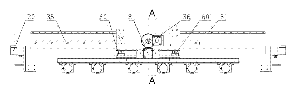
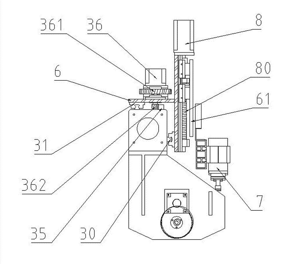
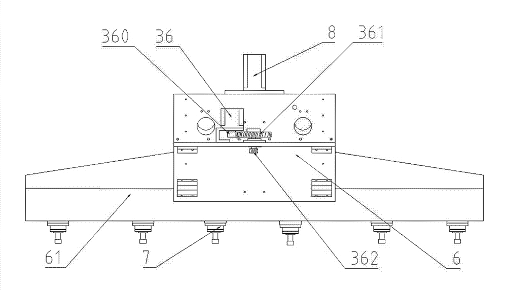
[0023] Such as Figure 1 to Figure 5 It can be seen that the present invention can be used as the gantry of the numerical control engraving machine.

[0024] The numerical control engraving machine includes a bed body 1, on which a left column 2 and a right column 2'are movably connected by a left guide rail 10 and a right guide rail 10', the left column 2, the right column 2 A Y-direction driving device is also arranged between the'and the bed body 1, and a gantry 3 is arranged above the left column 2, the right column 2', and an X-direction vertical guide 30 is arranged on the vertical surface of the gantry 3, and an X-direction vertical guide rail 30 is arranged on the horizontal surface. X-direction horizontal guide rail 31, the gantry 3 is movably provided with a mobile base 6 through the X-direction vertical guide rail 30 and X-direction horizontal guide rail 31. The mobile base 6 is composed of mutually perpendicular horizontal plates and vertical plates. The base left gu...

Embodiment 2

[0040] The difference from the first embodiment is that this embodiment uses a screw drive in the X direction.

[0041] by Image 6 It can be seen that the X-direction drive device includes an X-direction drive motor 32 set on the gantry 3, and also includes an X-direction screw 33 connected to the main shaft of the X-direction drive motor 32. The moving base 6 and the X-direction screw 33 pass Screw drive connection. Specifically, the cross section of the mobile base 6 is in the shape of "┠", which includes a horizontal plate and a vertical plate that are fixed to each other. The X-direction screw 33 is connected to the mobile base 6 in the middle below the horizontal plate, and the transmission is stressed. Evenly. In the present invention, the movable base 6 is connected by the X-direction vertical guide rail 30 and the X-direction horizontal guide rail 31 provided on two different end faces of the gantry 3. Therefore, in the X direction, the method of adjusting the partial t...


PUM


Abstract

The invention provides an integrated tool-setting type numerical-control engraving machine portal frame assembly which is high in travelling precision, good in engraving effect, long in service life and flexible in mounting mode and comprises a portal frame and an X-direction driving device arranged on the portal frame. An X-direction vertical guide rail is arranged on a vertical surface of the portal frame, an X-direction horizontal guide rail is arranged on a horizontal surface of the portal frame, a moving base is arranged on the portal frame through the X-direction vertical guide rail and the X-direction horizontal guide rail, the moving base is composed of a transverse plate and a vertical plate which are mutually perpendicular, an engraving head fixing plate is movably arranged on the moving base through a left base guide rail and a right base guide rail, a Z-direction driving device is arranged between the moving base and the engraving head fixing plate, and a plurality of engraving heads are arranged on the engraving head fixing plate.

Description

Technical field [0001] The invention relates to a CNC numerical control engraving machine, in particular to a numerical control plane engraving machine. Background technique [0002] The Chinese utility model patent with the authorized announcement number 202242712U discloses an X-direction driving device for a multi-head engraving machine, which includes a gantry. The sides of the gantry are provided with upper and lower X-direction square rails, and the upper end of the gantry is provided with an X-direction rack. At least one active engraving head is movably connected to the gantry through upper and lower X-direction square rails, and multiple engraving heads are movably connected to the gantry through upper and lower X-direction square rails; the active engraving head is provided with X-direction teeth. An X-direction motor connected by a gear; the active engraving head and a plurality of engraving heads are connected by connecting rods. The structure is simple, the movement...

Claims


Application Information

Patent Timeline
Patent Type & Authority Applications(China)
IPC IPC(8): B44B1/00B44B3/00
Inventor 汪洪涛
Owner 安庆市宏大涛业精啄数控科技有限公司
Why Eureka
Try Eureka