Vibrating direction angle adjustable two-mass vibrating feeder

A vibrating feeder and vibrating direction technology, which is applied to vibrating conveyors, conveyors, transportation and packaging, etc., can solve the problems of not being able to use the vibrating feeder, unevenness, and small feeding volume, and achieve novel structure, The effect of increasing the feeding amount and reducing the impact force

Inactive Publication Date: 2014-01-29
鹤壁市煤化机械有限责任公司
View PDF9 Cites 1 Cited by
  • Summary
  • Abstract
  • Description
  • Claims
  • Application Information

AI Technical Summary

Problems solved by technology

[0002] At present, in the vibrating feeders used in my country's metallurgy, coal, chemical industry, building materials, electric power, light industry and other industries, the vibration direction angle is fixed. In the process of conveying materials, the feeding amount is small and very unstable. Uniform, can not play the maximum potential of the vibrating feeder

Method used


Image

  • Vibrating direction angle adjustable two-mass vibrating feeder
  • Vibrating direction angle adjustable two-mass vibrating feeder
  • Vibrating direction angle adjustable two-mass vibrating feeder

Examples


Embodiment Construction

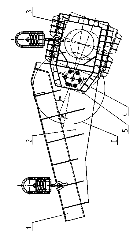
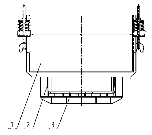
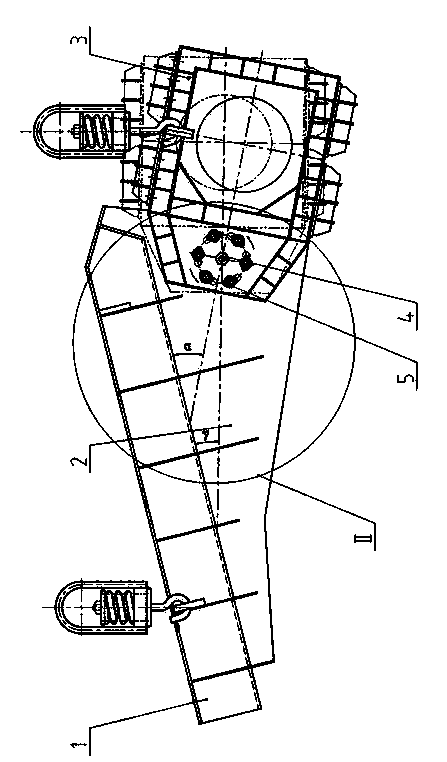
[0020] control Figure 1~6 , The double-mass vibrating feeder with adjustable vibration direction angle of the present invention is composed of a vibrating tank, a thrust plate, a vibrator, a central pin shaft and a fixing bolt. The vibration tank body 1 is welded with the thrust plate 2, and the thrust plate 2 is connected with the vibrator 3 through the fixing bolt 5 and the central pin shaft 4. At the joint between the thrust plate 2 and the vibrator 3, with the center pin 4 as the center of the circle, there are several circular bolt holes on the thrust plate 2, and on the vibrator 3, there are the same number of elongated bolt holes on the circumference. . The connection of the vibrator 3 and the thrust plate 2 is to fasten it together by each fixing bolt 5 and the central pin shaft 4 .

[0021] The working principle of the present invention is: in the figure, the angle α is the initial angle. When the vibration direction angle of the vibrating feeder needs to be increa...


PUM


Abstract

The invention discloses a vibrating direction angle adjustable two-mass vibrating feeder which completely solves the problem that the vibrating direction angle of an existing two-mass vibrating feeder is permanent. At present, the vibrating direction angle of the existing vibrating feeder used in Chinese industries such as metallurgy and coal is permanent, feeding quantity is small and very uneven in the material conveying process, the maximum potential of the vibrating feeder cannot be made full use of, and particularly, the feeding quantity is affected due to different running speeds of materials at the front end and the rear end of a long vibrating feeder. The vibrating direction angle adjustable two-mass vibrating feeder comprises a vibrating tank, a thrust plate, a vibrator, a center pin and fixing bolts. The vibrator and the thrust plate are fastened together by the fixing bolts and accordingly are connected. When the vibrating direction angle of the vibrating feeder needs to be enlarged, the fixing bolts are loosened, the vibrator rotates clockwise by a certain angle, and then the fixing bolts are fastened. Conversely, when the vibrating direction angle needs to be decreased, a vibration exciter rotates anticlockwise by a certain angle, and then the fixing bolts are fastened.

Description

technical field [0001] The invention relates to a two-mass vibrating feeder with adjustable vibration direction angle, which is mainly used for uniform feeding of bulk, granular or powdery materials in metallurgy, coal, chemical industry, building materials, electric power, light industry and other industries. field. Background technique [0002] At present, in the vibrating feeders used in my country's metallurgy, coal, chemical industry, building materials, electric power, light industry and other industries, the vibration direction angle is fixed. In the process of conveying materials, the feeding amount is small and very unstable. Even, the maximum potential of the vibrating feeder cannot be exerted. Especially for longer vibrating feeders, the front and rear ends of the feeder will affect the feeding amount due to the different running speeds of the materials. At present, mines especially need a two-mass vibrating feeder with adjustable vibration direction angle. By ad...

Claims


Application Information

Patent Timeline
IPC IPC(8): B65G27/32
Inventor 王运池桂建阁赵成群罗东平杜天泽
Owner 鹤壁市煤化机械有限责任公司
Why Eureka
Try Eureka