
Vacuum preloading method and vacuum preloading device for water-air separation

A technology of vacuum preloading and water-gas separation, which is used in soil protection, construction, infrastructure engineering, etc., to save construction energy consumption and improve the effect of vacuuming

Active Publication Date: 2014-01-29
GUANGZHOU SHENGZHOU FOUND ENG
View PDF5 Cites 14 Cited by
  • Summary
  • Abstract
  • Description
  • Claims
  • Application Information

AI Technical Summary

Problems solved by technology

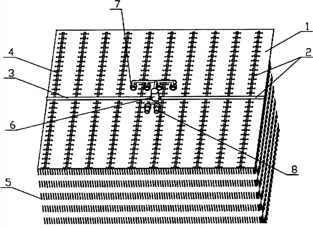
[0017] The main purpose of the present invention is to solve the problems of water-gas separation, water-gas transfer, and water-gas extraction in the vacuum preloading construction process, and use the water-gas separation pipeline and water-gas separation tank outside the sealing film to carry out water-gas separation, and in the In the case of water-gas separation, the water can flow by itself along the lower space of the water-gas separation pipeline, so that the upper space of the water-gas separation pipeline becomes a smooth channel for transmitting air and vacuum negative pressure, and the vacuum device is used respectively in the water-gas separation Pump out the air in the tank to generate vacuum negative pressure and use the pumping device to discharge the water in the water-gas separation tank to improve the effect of vacuum preloading soft ground treatment, reduce construction costs and shorten the construction period

Method used


Image

  • Vacuum preloading method and vacuum preloading device for water-air separation
  • Vacuum preloading method and vacuum preloading device for water-air separation
  • Vacuum preloading method and vacuum preloading device for water-air separation

Examples


Embodiment 1

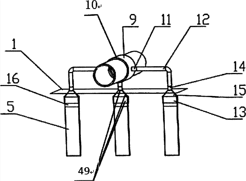
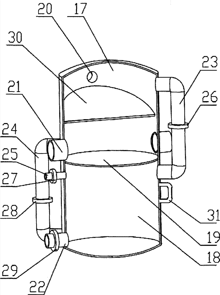
[0081] This embodiment illustrates the technical solutions of the water-gas separation vacuum preloading method, the three-piece connection device and the sub-compartment type water-gas separation tank with the water-gas separation pipeline connected to the plastic drainage board with reference to the accompanying drawings.

[0082] Such as figure 1 or figure 2 or image 3 As shown, for an area of ​​200m×200m, a total of 40000m 2 Water and gas separation vacuum preloading is carried out in the rectangular soft foundation treatment area, and the vacuum degree under the vacuum sealing film is required to reach 80Kpa.

[0083] When the plastic drainage board (5) is constructed in the soft foundation treatment area according to the traditional vacuum preloading construction method, the plastic drainage board (5) is inserted in parallel in a square at a distance of 1m×1m along one side of the rectangular site.

[0084] The connection between the plastic drainage board (5) and t...

Embodiment 2

[0115] This embodiment illustrates the installation of the water-gas separation pipeline under the vacuum preloading method in which the vacuum branch pipe (4) of the water-gas separation pipeline (2) is connected to the vacuum tube (46) under the vacuum sealing film (1) in conjunction with the accompanying drawings. (2) The technical solution. In this embodiment, the installation of the water-gas separation tank (6), the vacuuming device (7) and the water pumping device (8), as well as the construction of the vacuuming and drainage consolidation operations are carried out with reference to the technical scheme of the first embodiment.

[0116] Such as Figure 4 or Figure 5 As shown, for an area of ​​100m×200m, a total of 20000m 2 Water and gas separation vacuum preloading is carried out in the rectangular soft foundation treatment area, and the vacuum degree under the vacuum sealing membrane (1) is required to reach 80Kpa.

[0117] According to site conditions and design ...

Embodiment 3

[0123] This embodiment illustrates the installation of the water-gas separation pipe for the water-gas separation vacuum preloading method in which the vacuum branch pipe (4) of the water-gas separation pipeline (2) is connected to the filter tube (44) under the vacuum sealing film (1) in conjunction with the accompanying drawings The technical scheme of road (2). In this embodiment, the installation of the water-gas separation tank (6), the vacuuming device (7) and the water pumping device (8), as well as the construction of the vacuuming and drainage consolidation operations are carried out with reference to the technical scheme of the first embodiment.

[0124] Such as Figure 6 or Figure 7 As shown, for an area of ​​50m×100m, a total of 5000m 2 Water and gas separation vacuum preloading is carried out in the rectangular soft foundation treatment area, and the vacuum degree under the vacuum sealing membrane (1) is required to reach 80Kpa.

[0125] According to site cond...


PUM

PropertyMeasurementUnit
Lengthaaaaaaaaaa
Diameteraaaaaaaaaa
Wall thicknessaaaaaaaaaa

Abstract

Disclosed are a vacuum preloading method and a vacuum preloading device for water-air separation. The vacuum preloading method includes that water-air separation pipelines, water-air separation tanks, a vacuumizing device and a water pumping device are mounted on the outer side of a vacuum sealing film, so that water pumped out from the soil mass of a soft ground treatment area and air are subjected to water-air separation in the water-air separation pipelines; the upper portions of the water-air separation pipelines are delivery channels for vacuum negative pressure and the air, and the water is allowed to flow into the water-air separation tanks along the lower portions of the water-air separation pipelines to be vacuumized and pumped through the vacuumizing device and the water pumping device respectively. A three-in-one type connecting device of plastic drainage plates and the water-air separation pipelines comprises a plastic drainage plate joint, a connecting pipe and a reducing-tee multipass joint, a bin-split type water-air separation tank is provided with an upper sealed cabin and a lower sealed cabin, and a gravity drainage type water-air separation tank comprises a tubular tank body and a drill bit, and a sinking pump is mounted at the lower end of the tank body. The vacuum preloading method and the vacuum preloading device have the advantages that vacuum preloading construction cost can be reduced, construction quality is improved, and construction period is shortened.

Description

technical field [0001] The invention discloses a method and device for vacuum preloading soft ground treatment, in particular a vacuum preloading method and device for water and gas separation. Background technique [0002] Vacuum preloading soft ground treatment method is a widely used large-area soft ground treatment method. [0003] The main construction steps of the existing vacuum preloading soft ground treatment method are: [0004] 1) Establish a vertical drainage channel: that is, insert a plastic drainage board vertically in the soft foundation treatment area; [0005] 2) Establish a horizontal drainage channel: that is, lay medium-coarse sand, filter pipes, and vacuum pipes horizontally in the soft foundation treatment area, or only lay vacuum pipes horizontally and connect or overlap the vacuum pipes and plastic drainage plates; [0006] 3) Establish a vacuum preloading sealing system: construct a mud mixing pile sealing wall or excavate a sealing ditch around t...

Claims


Application Information

Patent Timeline
IPC IPC(8): E02D3/10
Inventor 邓立新
Owner GUANGZHOU SHENGZHOU FOUND ENG
Learn More