
A rotor spinning machine

A technology of rotor spinning machine and rotor seat, which is applied in spinning machine, open-end spinning machine, continuous winding spinning machine, etc., can solve the problem of different application scope and limit the variety of rotor spinning and other problems, to achieve the effect of improving evenness, feeding and carding efficiency, and feeding speed.

Active Publication Date: 2016-07-06
DONGHUA UNIV +1
View PDF3 Cites 0 Cited by
  • Summary
  • Abstract
  • Description
  • Claims
  • Application Information

AI Technical Summary

Problems solved by technology

Due to the single-set carding characteristics of the traditional spinning device, the rotor spinning has a greater application in cotton spinning products, but at the same time, the rotor spinning is also used to produce blended yarns, short and thick slub yarns, fancy yarns, etc. Larger limitations and problems with new yarns
The main reason is that different types of carding rollers have different application ranges for raw materials, and it is difficult for the same carding device to card fibers with different properties at the same time. Therefore, to a certain extent, it limits the variety of rotor spinning varieties. sex

Method used


Image

  • A rotor spinning machine
  • A rotor spinning machine
  • A rotor spinning machine

Examples


Embodiment Construction

[0043] The present invention will be further described below in combination with specific embodiments. It should be understood that these examples are only used to illustrate the present invention and are not intended to limit the scope of the present invention. In addition, it should be understood that after reading the content taught by the present invention, those skilled in the art may make various changes or modifications to the present invention, and these equivalent forms also fall within the scope defined by the appended claims of the present application.

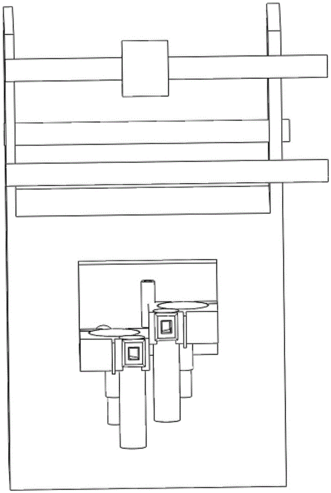
[0044] A kind of rotor spinning machine of the present invention, as figure 1 Shown: It is composed of a frame, a transmission device, a yarn drawing device, a suction device and a spinning device.

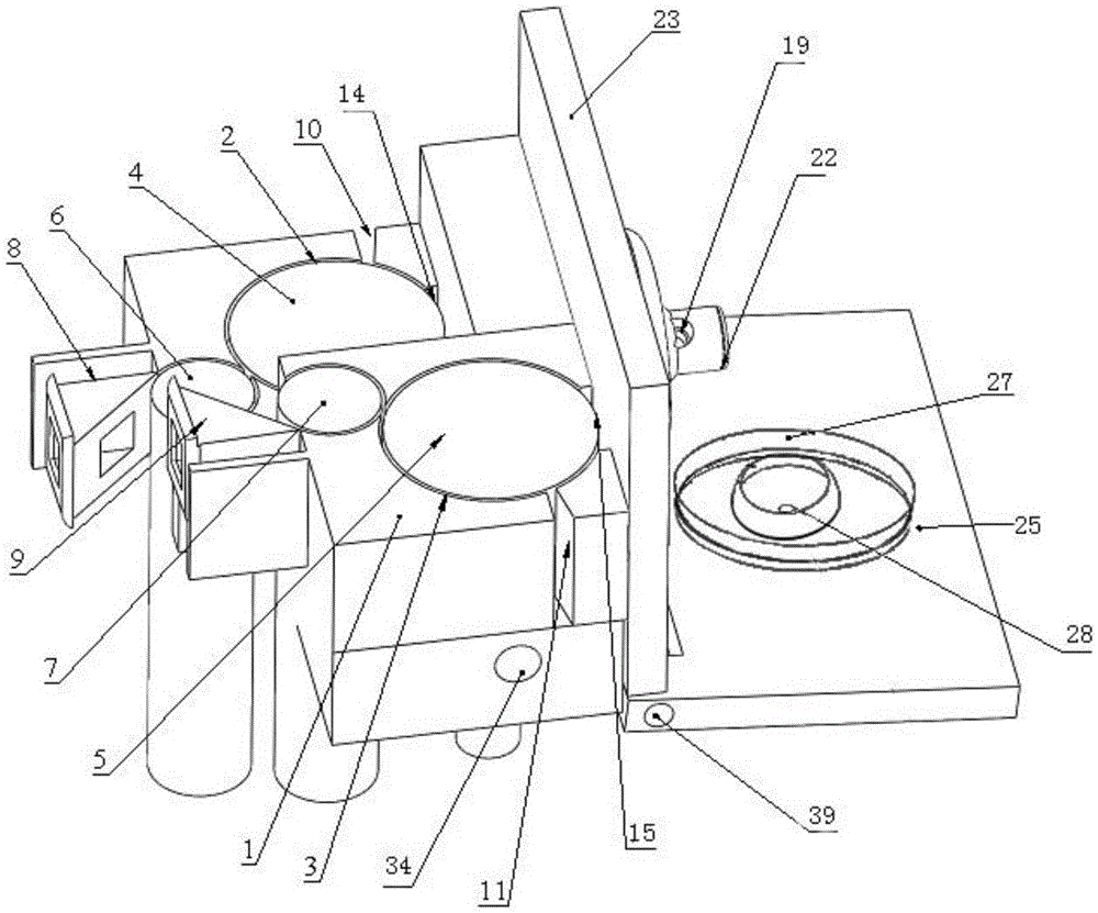
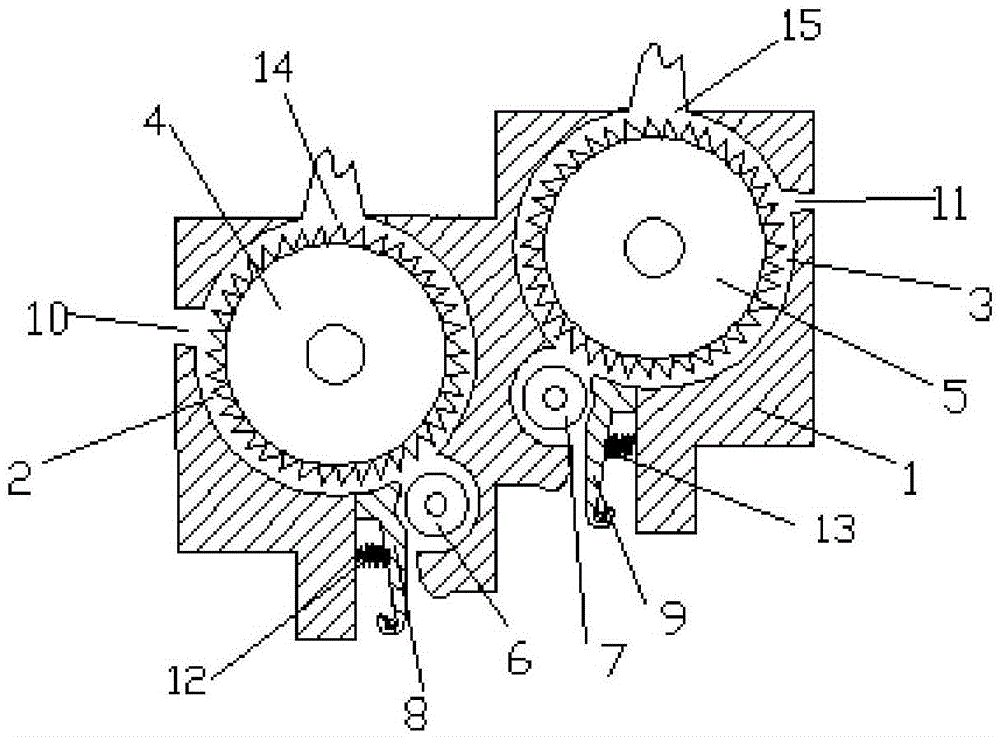
[0045] A kind of rotor spinning machine as mentioned above, such as figure 2 Shown: including a housing (1) with a left opening chamber (2) and a right opening chamber (3) and a cup holder (25);

[0046] Such as i...


PUM


Abstract

The invention relates to a spinning machine, in particular to a rotor spinning machine which is characterized by comprising a framework, a transmission gear, a yarn guide device, an induced draft device, a spinning apparatus and the like. Two feeding devices and two carding devices of the spinning apparatus of the rotor spinning machine are arranged side by side, and the spinning apparatus is provided with two channels and a single rotor. The two carding devices and the two feeding devices are respectively arranged on the left side and the right side of a shell of the spinning apparatus and are alternately arrayed, and individual transmission effects are respectively realized for the feeding devices and the carding devices; the two channels are respectively matched with the two carding devices and are respectively connected with the rotor by yarn outlets. The rotor spinning machine has the advantages that shortcomings in the aspects of the structure and the performance of an existing rotor spinning apparatus can be overcome by the spinning apparatus of the rotor spinning machine, the original single-silver feeding and carding mode is replaced by a double-silver feeding and carding mode for rotor spinning, accordingly, varieties of rotor spinning yarns can be increased, the quality of the rotor spinning yarns can be improved, and the rotor spinning speed can be effectively increased.

Description

technical field [0001] The invention belongs to the technical field of spinning machines, relates to a spinning machine, in particular to a rotor spinning machine, specifically two sets of feeding and carding devices, two channels and only one rotor spinning machine. Rotor spinning machine for rotor spinning. Background technique [0002] With the rapid development of the textile industry and the continuous improvement of the level of automation, various new spinning methods have emerged. Among them, due to its high spinning speed, large package capacity, good spinnability, and the ability to spin high-quality low-grade raw materials and low-grade raw materials, the rotor spinning machine has become the most mature and widely used spinning technology in the new spinning technology. The spinning form with the widest range and high economy. Since it was put into large-scale industrial application in the 1970s, after more than 40 years of development, rotor spinning products ...

Claims


Application Information

Patent Timeline
Patent Type & Authority Patents(China)
IPC IPC(8): D01H4/06D01H4/38D01H4/32
Inventor 汪军虞叔良闫进祥张玉泽傅婷龚以炜
Owner DONGHUA UNIV
Learn More