
Metallic card wire

Active Publication Date: 2014-09-18
GROZ BECKERT KG
View PDF13 Cites 9 Cited by
  • Summary
  • Abstract
  • Description
  • Claims
  • Application Information

AI Technical Summary

Benefits of technology

The invention provides a cylinder wire for revolving flat cards that can better take fibers after being resharped one or more times, resulting in improved carding performance. The card wire has a tip angle of up to 30 degrees, preferably 25 degrees, which facilitates penetration into fiber bundles and improves carding.

Problems solved by technology

However the creation of a flat surface at the tip of the wire cannot be avoided.
This flat surface means that the tooth has lost sharpness compared to its initial state and hence that carding performance is reduced in that fibres can less easily be taken (e.g. from the revolving flats) by the teeth of the card wire.
It is another drawback of these wires that the platform (in CN201258379Y) or the one hump (in the “camel type” card wire) is at a distinctly lower position than the tip of the tooth.
This fact can cause a lot of fibre rolling instead of fibre carding and hence the undesirable creation of fibre neps.

Method used


Image

  • Metallic card wire
  • Metallic card wire
  • Metallic card wire

Examples


Embodiment Construction

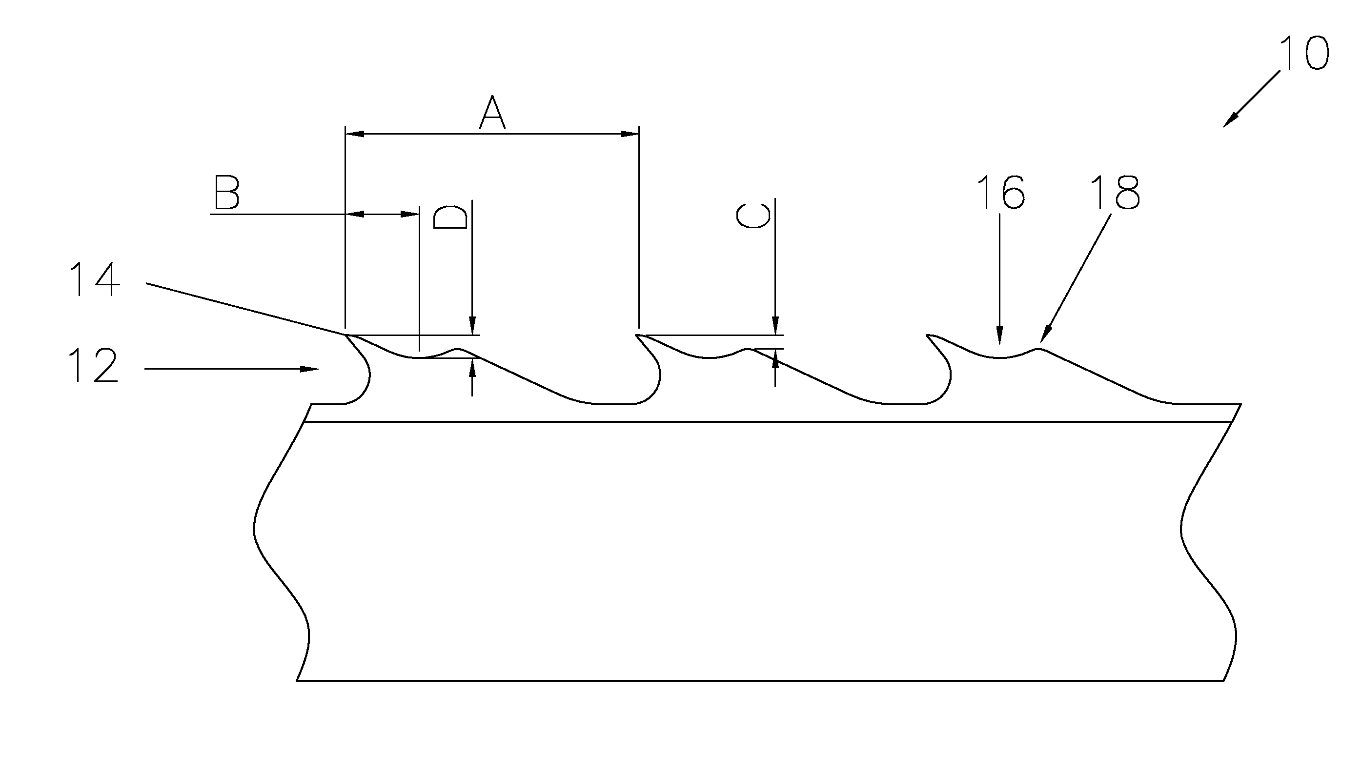
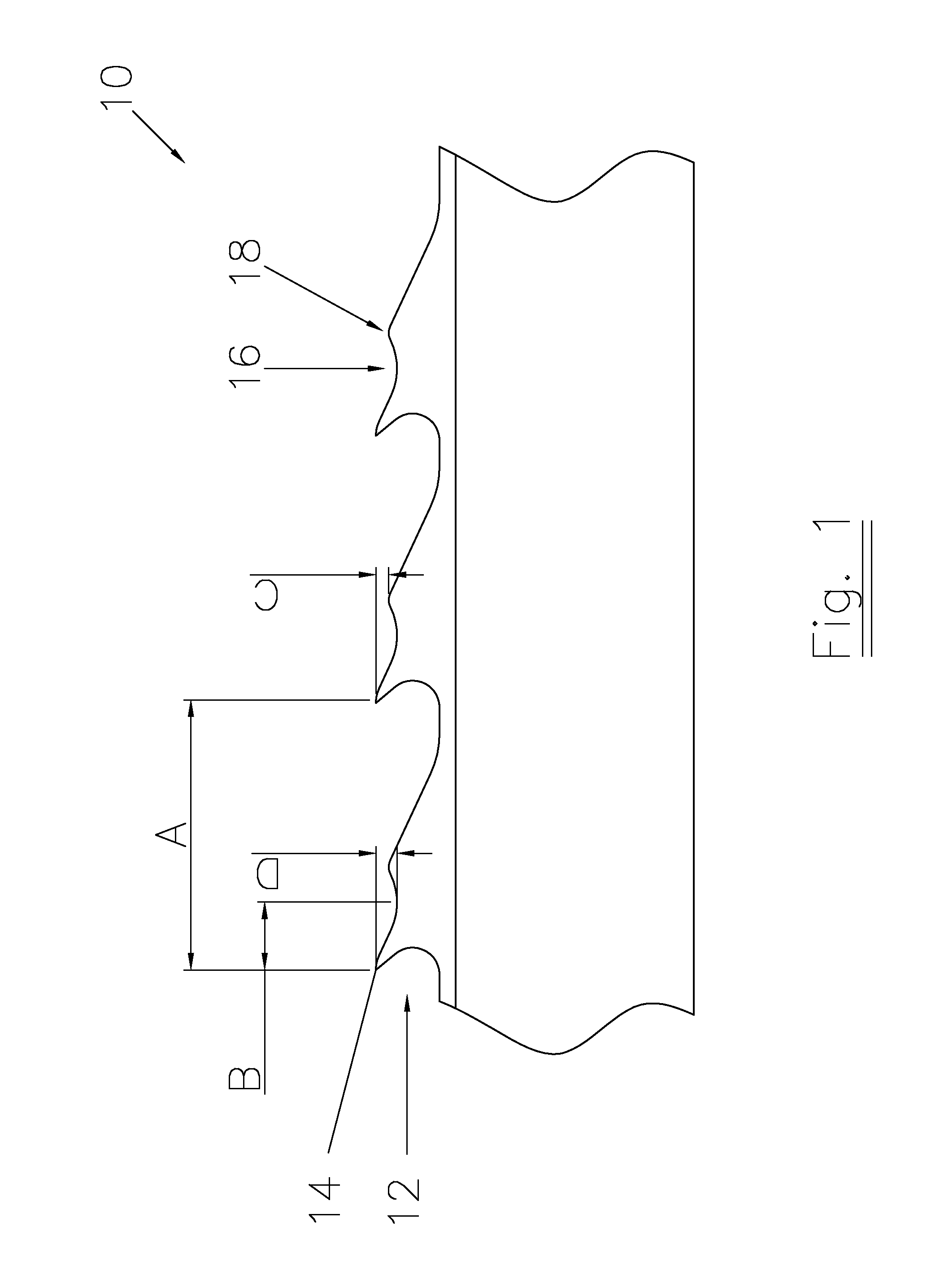
[0043]FIG. 1 shows a camel type wire 10 according to the prior art. The card wire has a front segment 12 with a tip 14. The wire has at its top segment a valley 16 followed by a hump 18. In an example the card wire has a pitch A of 1.70 mm, a distance along the length direction of the wire B between the tip and the hump of 0.3878 mm. The vertical distance C between the hump and the tip is 0.08 mm. The vertical distance D between the valley and the tip is 0.65 mm.

[0044]FIGS. 2-5 show examples of card wires according to the first aspect of the invention. The card wires of these examples can be made using rotary punching, but can also be made via vertical punching.

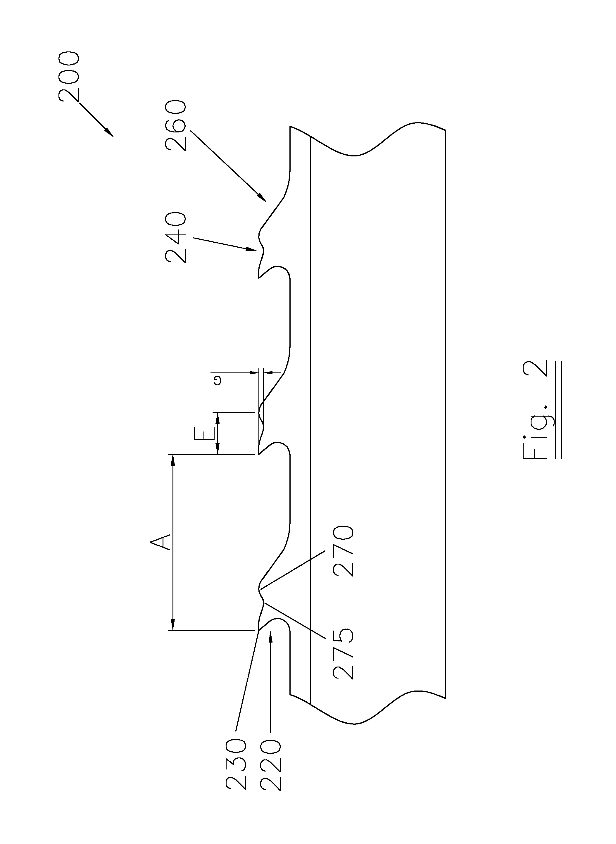
[0045]FIG. 2 shows a metallic card wire 200 according to the first aspect of the invention and with one hunch in the top segment. The card wire has a front segment 220 (with a tip 230) and a top segment 240 and a back segment 260. The top segment 240 comprises one hunch 270 and a valley 275. In an example the card wire has a ...


PUM

PropertyMeasurementUnit
Lengthaaaaaaaaaa
Fractionaaaaaaaaaa
Angleaaaaaaaaaa

Abstract

A metallic card wire has an elongated rib portion and teeth. The teeth have a front segment, a top segment and a back segment. The front segment has the connection of the tooth from the elongated rib portion and the front segment including a tip which is actively taking fibres in carding. The top segment has at least one hunch after the tip in the direction of the back segment. If more than one hunch is present the first hunch is the hunch positioned closest to the tip; if only one hunch is present this hunch is the first hunch. The back segment forms the connection of the top segment towards the elongated rib portion and the front segment of the next tooth.

Description

TECHNICAL FIELD[0001]The invention relates to a card wire. The new card wire can e.g. be used on cylinders on revolving flat cards. Other applications include lickerin rollers on roller cards and on revolving flat cards as well as cylinders on roller cards. The invention describes a method to make such card wires as well.BACKGROUND ART[0002]In issue No 25 (08 / 2011) of the magazine “Spinnovation”, a “camel type” card wire is proposed for use on cylinder and lickerin rollers of revolving flat cards. The tooth has a tip which has the traditional shape, and in addition to it one hump at the back of the tooth at a distance from the tip of the tooth and positioned considerably lower than the tip of the tooth. Such a wire is shown in FIG. 1. The claimed benefit of the camel shape is a positive effect on the airflow on the clothing surface. And as a result, the fibres are kept on the surface of the cylinder wire much better, thus preventing the fibres from sliding into the clothing. The clo...

Claims


Application Information

Patent Timeline
IPC IPC(8): D01G15/88B23D65/02
CPCB23D65/02D01G15/88Y10T83/9442
Inventor ZHANG, YUNING
Owner GROZ BECKERT KG
Learn More