Air nozzle manufactured by adopting base sectional material combination and manufacturing method thereof
A profile and basic technology, which is applied to the tuyere and its manufacturing field made by the combination of basic profiles, to achieve the effect of high precision and consistency, and improve manufacturing efficiency
- Summary
- Abstract
- Description
- Claims
- Application Information
AI Technical Summary
Problems solved by technology
Method used
Image

Examples
Embodiment 1
[0052] The manufacturing method of the air outlet nozzle on one side of the embodiment comprises the following steps:
[0053] Step 1. Manufacture a corresponding mold according to the structure of the basic profile 1 of the side air outlet nozzle.
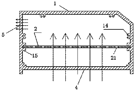
[0054] Step 2. Using a die-casting machine to die-cast the basic profile 1 through a preset mold, the two side walls of the basic profile 1 are open, and the screw bottom holes 14 for connecting the end plates 3 are cast in the openings.
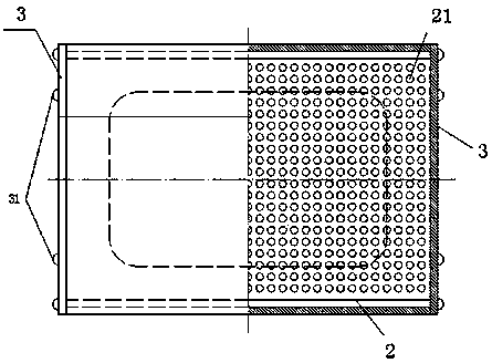
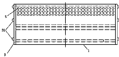
[0055] Step 3, the air outlet 5 and the air inlet 4 are processed on the outer wall of the basic profile 1 . The air outlet 5 of the side air outlet nozzle is processed on the top of the side wall of the base profile 1, and the air inlet 4 is processed on the bottom of the base profile 1. like image 3 As shown, in this embodiment, the air outlet 5 is set as a composite structure in which multiple through holes are drilled on the upper part of the side wall of the base profile 1 .
[0056] Step...
Embodiment 2
[0065] Embodiment 2, the manufacturing method of the upper outlet air nozzle comprises the following steps:
[0066] Step 1. Manufacture a corresponding mold according to the structure of the basic profile 1 of the upper air outlet nozzle.
[0067] Step 2. Using a die-casting machine to die-cast the basic profile 1 through a preset mold, the two side walls of the basic profile 1 are open, and the screw bottom holes 14 for connecting the end plates 3 are cast in the openings.
[0068] Step 3, the air outlet 5 and the air inlet 4 are processed on the outer wall of the basic profile 1 . The air outlet 5 of the side air outlet nozzle is processed on the top of the base profile 1, and the air inlet 4 is processed on the bottom of the base profile 1. like Image 6 As shown, the air outlet 5 in this embodiment is set as a composite structure in which multiple through-holes are drilled on the top of the base profile 1 .
[0069] Step 4. Press the aluminum plate whose edge shape str...
Embodiment 3
[0079] In the third embodiment, the manufacturing method of the inclined outlet air nozzle includes the following steps:
[0080] Step 1. According to the structure of the basic profile 1, respectively manufacture molds for die-casting the air inlet unit 11, the air distribution plate unit 12 and the air outlet unit 13.
[0081] Step 2: Die-cast the air inlet unit 11 , the air distribution plate unit 12 and the air outlet unit 13 that make up the basic profile 1 by using a die-casting machine through a preset mold.
[0082] An air distribution plate 121 integrally formed with the air distribution plate unit is prefabricated in the inner cavity of the air distribution plate unit 12, and the inner cavity of the air distribution plate unit 12 is divided into two chambers respectively communicating with the air outlet unit 13 and the air inlet unit 11. The air-distributing plate 121 is provided with an air-distributing through hole.
[0083] After the die-casting process is compl...
PUM
 Abstract
Description
Claims
Application Information
 - Generate Ideas
- Intellectual Property
- Life Sciences
- Materials
- Tech Scout
- Unparalleled Data Quality
- Higher Quality Content
- 60% Fewer Hallucinations
Browse by: Latest US Patents, China's latest patents, Technical Efficacy Thesaurus, Application Domain, Technology Topic, Popular Technical Reports.
© 2025 PatSnap. All rights reserved.Legal|Privacy policy|Modern Slavery Act Transparency Statement|Sitemap|About US| Contact US: help@patsnap.com